Measuring Amp Draw
Some locations may choose to do this procedure on a more frequent basis (i.e., quarterly, semi-annually, or other frequency).
To identify if there are issues with cooking performance or oil recovery caused from issues with the heat system. This inspection will be accomplished by measuring amp draw at each of the 6 heating elements (3 heaters in each of the two heating element assemblies) and comparing that reading with the “Amps per heater” number. that matches the voltage of the unit being inspected.
| Volts | Phase | Hertz | kW | Unit Amp Draw | Amps per heater |
|---|---|---|---|---|---|
| 200 | 3 | 50 or 60 | 17.0 | 49.0 | 14.1 |
| 208 | 3 | 60 | 17.0 | 47.2 | 13.6 |
| 240 | 3 | 60 | 17.0 | 40.9 | 11.8 |
| 380 | 3 | 50 | 17.0 | 25.8 | 12.9 |
| 400 | 3 | 50 | 17.0 | 24.6 | 12.3 |
| 415 | 3 | 50 | 17.0 | 23.7 | 11.9 |
| 480 | 3 | 60 | 17.0 | 20.5 | 5.9 |
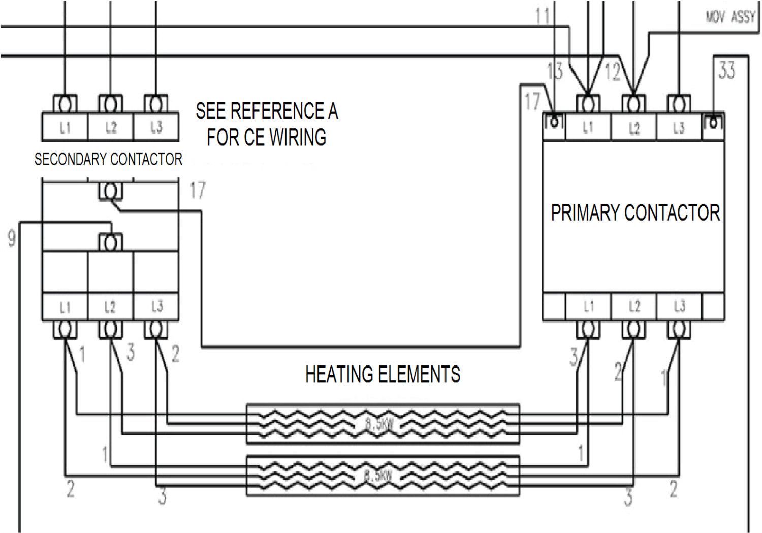
Checking Amp Draw for 200, 208, 240 and 480 volt units
-
With voltage disconnected from the fryer, attach an amp clamp to wire 1 connected to the secondary contactor at the upper heating element.
-
Re-connect voltage to the fryer and select a product to allow the fryer to call for heat. Once heating, make a note of the wire being checked and the amp draw from the amp clamp.
Example: Wire 1 Amp Reading 13.2
-
Repeat steps 1 and 2 for wires 2 and 3 for the upper heater and then for wires 1, 2 and 3 for the lower heater. Remember to note amp draw for each wire.
-
Compare the noted readings with the “Amps per heater” column in Table 1. that matches the voltage of the fryer. If all voltage readings are within 10% of this number, the heat circuit is working properly and passes inspection. If one or several of the wires tested does not match, troubleshoot to narrow down whether there are issues with incoming voltage, contactor(s), or heating element assemblies.
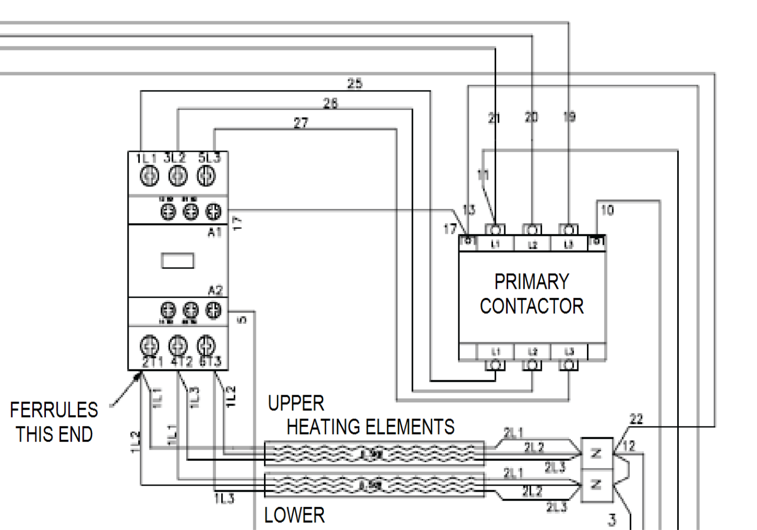
Checking Amp Draw for 380, 400 or 415 volt units
-
With voltage disconnected from the fryer, attach an amp clamp to wire 1L1 at the upper heating element.
-
Re-connect voltage to the fryer and select a product to allow the fryer to call for heat. Once heating, make a note of the wire being checked and the amp draw from the amp clamp.
Example: Wire 1L1 Amp Reading 12.7
-
Repeat steps 1 and 2 for wires 1L2 and 1L3 for the upper heater and then for wires 1L1, 1L2 and 1L3 for the lower heater. Remember to note amp draw for each wire.
-
Compare the noted readings with the “Amps per heater” column in Table 1. that matches the voltage of the fryer. If all voltage readings are within 10% of this number, the heat circuit is working properly and passes inspection. If one or several of the wires tested does not match, troubleshoot to narrow down whether there are issues with incoming voltage, contactor(s), or heating element assemblies.