Replacing the High Temperature Limit
A high limit thermocouple is attached to each element and senses oil temperature. If temperature exceeds 600°F (316°C), a switch opens and shuts off heat to vat, and an E-10 error code is displayed. After oil temperature cools to a safe operating temperature (15-20 min.), the high limit must be manually reset.
High limit reset switches are located in the front edge of an electrical panel on the left side of the unit beside the filter pan. Open the left door, depress the raised part of the rocker switch for the affected well, and release switch. If high limit resets, the oil starts heating. If high limit does not reset, perform following checkout procedure.

|
To avoid electrical shock or property damage, move the power switch to OFF and disconnect power. |
Checkout
-
Open left door and remove the filter pan.
-
Remove 1 screw and panel cover.
-
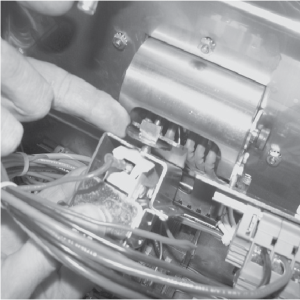
Locate the affected high limit control module and view the LEDs.
-
Are the LEDs alternate flashing? If yes, check the wiring between the high limit probe and the high limit control module for continuity. If the LEDs are not alternate flashing proceed to step 7.
-
Did the wiring pass continuity check? If yes, proceed to the next step. If no, repair/replace wiring.
-
Replace high limit probe (instructions on next page).
-
Are the LEDs simultaneously flashing? If yes, check the other high limit modules for flashing LEDs. If no, proceed to step 9.
-
Does more than one high limit module have LEDs flashing simultaneously? If yes, the temperature in the left compartment is too hot. Find the cause of the excessive heat and fix the problem. If no, replace the high limit control module (instructions below).
-
Check the wiring between the high limit control module and the high limit reset switch for continuity. If the wiring passed the continuity check replace the high limit reset switch (instructions below). If the wiring failed the continuity check repair/replace wiring.
Replacing the High Limit Module
-
Remove all electrical power from the fryer.
-
Tag and remove lead wires to control module.
-
Using 3/8“ socket, remove 2 nuts securing module to panel.
-
Install a new control module in reverse order.
Replacing the High Limit Reset Switch
-
Remove all electrical power from the fryer.
-
Open left door and remove the filter pan.
-
Remove 1 screw and panel cover.
-
Push in on spring tabs and pull the switch away from the mounting area.
-
Tag and remove the switch wires from the high limit module.
-
Tag and remove the wires from the high limit reset switch.
-
Install a new high limit reset switch in reverse order.
If the tube is broken or cracked, the control opens, shutting off electrical power. The control cannot be reset.
-
Using a crosshead screwdriver, or screw gun, remove the rear panel (9 screws).
-
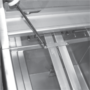
Using 3/8” wrench or socket, remove the 2 acorn nuts securing bracket to unit.
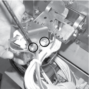
-
Using a crosshead screwdriver, remove the 2 screws securing the high limit to the bracket.
-
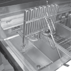
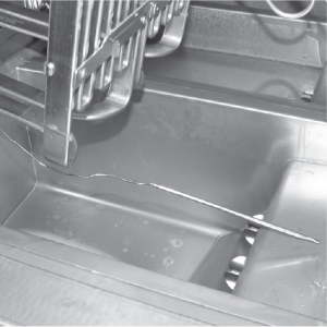
Use the lift tool and lift the hinged element from the vat.
NOTICE -
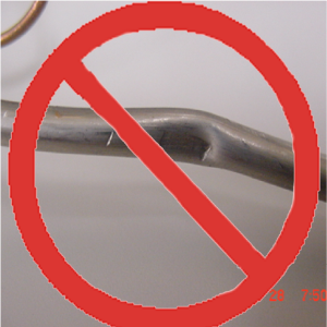
To avoid equipment damage, do not use element lifting tool near the high limit bulb.
-
Pull the high limit from the bracket, pull back the cardboard protector, and remove the two electrical wires from the high limit control.
-
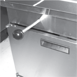
Pull-out on the drain valve knob and drain the oil from the vat.
-
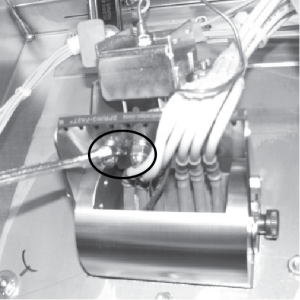
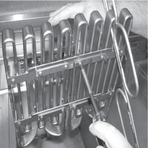
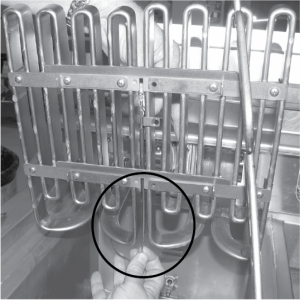
While holding the top-side capillary bracket, use a crosshead screwdriver and remove the screws securing the capillary bulb to the lower element bracket.
-
Remove both front and rear capillary brackets.
-
Using a crosshead screwdriver, remove the screws securing the capillary bulb to the upper element brackets.
-
Remove high limit bulb from element and carefully straighten the capillary tube and pull the high limit control from the rear of the unit.
NOTE: It’s important not to damage the capillary bulb when removing or installing the high limit from the unit. Undamaged high limits returned for warranty can be evaluated for cause of failure.
Capillary bulbs or tubes damaged during installation causes high limit to fail prematurely.
-
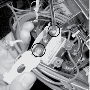
Insert new high limit capillary through hole in rear of fryer and slide high limit into bracket and then secure with the 2 screws.
-
Slide bracket and high limit assembly into place, making sure a 1/8 inch (2-3mm) gap remains between the red high limit button and the reset place, and then secure with the 2 acorn nuts removed in step 3.
-
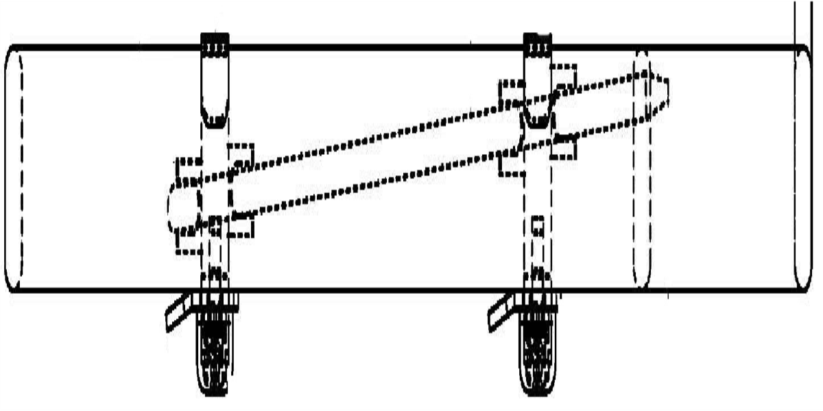
Carefully slide capillary bulb up through the element, from the rear of the elements.
-
Using the capillary brackets removed in step 3 (see below), attach the capillary to the lower brackets, aligning the capillary so it does NOT touch the element.
-
Secure the capillary to the upper brackets.
-
Replace rear cover and reconnect power to vat.
-
Lower element back into vat and close drain. Fill vat by pressing and holding the filter button until *FILTER**MENU* displays. Then once “1. EXPRESS FILTER” displays, press the right arrow button four times until “5.FILL FROM PAN” displays. Press √ button and “PUMP” “EXIT” displays. Press √ button again, and oil fills vat. Once vat is full, press X twice to return to normal operation.