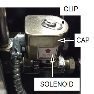
Inspecting the Solenoid Valve
Some locations may choose to do this procedure on a more frequent basis (i.e., quarterly, semi-annually, or other frequency).

|
To avoid electrical shock or property damage, move the power switch to OFF and disconnect power. |
|
|
Only perform this procedure when the unit is cool or severe burns may result. |
Ensure the solenoid valve is undamaged and working within specification by doing the following:
-
Use a small flat blade screw driver to pry up on the center clip, and then slide off.
-
Slide the cap and coil assembly up off of the shaft.
-
Remove the top cap, and note the spring washer inside.
-
Place the cap and spring in a safe location so they are not lost.
-
Hang the lower cup and coil assembly to the side.
-
Using a 7/16 inch wrench to break the four hex head screws loose, remove and lay aside.
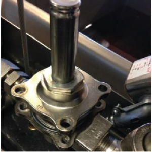
Solenoid bonnet shown with four screws removed.
-
Lift the bonnet up and off the plunger and lay aside.
-
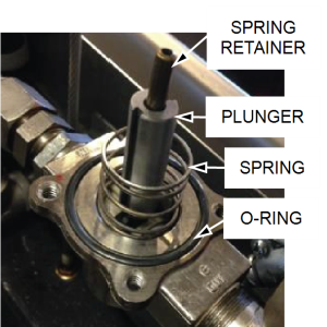
Remove the small spring retainer, plunger, large spring, and o-ring and lay aside.
The spring pulls out of the top of the plunger, and the plunger pulls out of the Valve Guide and Valve Seat. If a component is damaged or worn beyond specification, replace it.
-
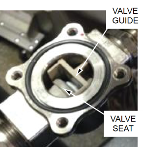
Remove the valve guide by pulling it straight up.
-
Slide the valve seat out, and then pull it out of the valve body.
-
Clean and inspect both of these components.
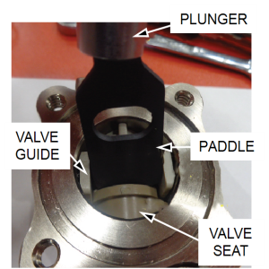
The Valve Guide is comprised of three separate pieces, a seat, spring and frame. The longer end of the frame goes down. The Valve Seat must be installed with the length of the rectangular hole in the horizontal position so it matches the paddle end of the plunger. If a component is damaged or worn beyond specification, replace it.
-
Reinstall the valve seat in the solenoid valve body.
Ensure the rectangle opening is oriented horizontally in the valve body. This ensures the beveled lip is pointing up, which is necessary when inserting the plunger.
-
Assemble the valve guide (frame + seat + seat) by inserting the longer end into the valve body, keeping the seat compressed so it slides past the valve seat.
-
Press the plunger’s paddle end down between valve guide and valve seat.
-
Ensure the plunger slides up and down freely.
-
Insert the small spring and retainer into the top of the plunger.
The Valve Guide is comprised of three separate pieces, a seat, spring and frame. The longer end of the frame goes down. The Valve Seat must be installed with the length of the rectangular hole in the horizontal position so it matches the paddle end of the plunger. Also, there is a bevel that must be positioned upward so the paddle can be inserted between the Valve Guide and Seat.
-
Install the o-ring into the valve body’s o-ring groove.
-
Place the large spring over the plunger and seat into the valve body.
-
Place the bonnet over the spring and retainer, plunger and large spring, and then press the two halves together.
-
Using a nut driver, install the four 7/16 inch hex head screws with captive star lock washers.
-
Snug the hex head screws with a 7/16 inch wrench in a star pattern to evenly seal the o-ring between both halves of the valve body.
-
Reinstall the coil over the bonnet with the conduit on the left side so it does not interfere with the lid cables.
-
Reinstall the spring washer and top cap over the coil.
-
Install the clip on top of the cap and coil.