Applies to:
![]()
Heat Theory of Operation
The heat system consists of 4 main components;
-
12 radiant heaters
-
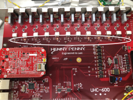
I/O board
-
Built-in temperature probes (one for each heater)
-
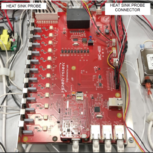
Heat sink temperature probe
The I/O board monitors the temperature of each heater by a built-in temperature probe (non-replaceable).
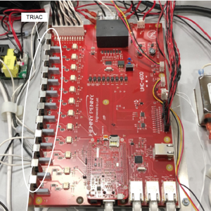
When the control signals 6 different shelves to heat to a desired setpoint temperature, the I/O board will energize the appropriate heaters with line voltage through Triacs (non-replaceable) mounted on the I/O board.
A LED light will turn on next to the energized Triac . Once that Triac is energized, line voltage is sent out to either the top heater, bottom heater, or both heaters of a shelf to maintain the desired temperature.
During start-up, a specific algorithm is used to heat the unit to setpoint. During this time, it will energize at most 9 heaters at one time. However, it will cycle back and forth between all the 12 heaters throughout the start-up process. Only energizing 9 of the 12 heaters at one time prevents the unit from the exceeding allowable amperage.
The purpose of the heat sink probe is to monitor the temperature of the heat sink for the 12 heater Triacs protecting them from overheating. An E-4B error code will be generated if the heat sink probe is overheated.
If a heater or shelf becomes too hot or does not maintain temperature, an error code of E-5, 215 or 216 will be generated into the error logs and the shelf will be disabled.
Related Content
Reference