Applies to:
![]()
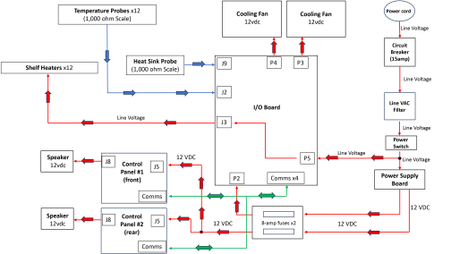
Heat Sequence of Operation
| Step | Description | Error or Fault If Step Fails |
|---|---|---|
|
1 |
Line voltage enters the unit through the power cord and goes through a line filter before voltage comes to the power switch. |
No Display |
| 2 | After the power switch is turned on, line voltage is now present at both the power supply board and the I/O board (P5 connector). NOTE: Line voltage at I/O board is for the shelf heaters. | No Display |
| 3 | Power Supply Board converts incoming line voltage to 12vdc to power the I/O board and each control. | No Display |
| 4 | There is an 8 amp fuse between the power supply and I/O board and an 8 amp fuse between the power supply and control boards. These fuses protect the power supply board from over amperage. |
No Display |
| 5 | Controls power up. Both board enclosure cooling fans are energized with 12vdc from the I/O board at connectors P3 and P4 to keep board enclosure cool. NOTE: Fans energize for 2 seconds and then pause for about 20 seconds at power up. | E-210 or E-4A |
|
6 |
Input of the 12 temperature probes comes into the J2 connector on the I/O board. |
E-6A or E-6B |
| 7 | Tap GO menu. Units starts to heat. If setpoint temperature from the control is not satisfied, then the I/O board will energize the appropriate heaters using built-in Triacs (x12) on I/O board with line voltage through the J3 connector. A LED light will illuminate on the I/O board next to the Triac to indicate that heater is energized. | E-216 |
| 8 | A heat sink probe monitors the heat released by the Triacs on the I/O board. If this probe becomes too hot, the unit will not heat. | E-4B |
| 9 | Once the shelf setpoint temperature is reached, the control panel will change from an orange to a light gray. Product can be loaded. | E-216 or E-215 |
Related Content
Reference