Replacing Vacuum Switch
-
Basic hand tools
-
Drill with crosstip bit
-
Needle nose pliers
-
Wire cutters
-
Crimping tool
-
Vacuum switch, .11 in. WC, vertical
-
Flag terminal, 18-22 GA, Qty 2
-
Screw, #8 x 1/2 crosstip, Qty 2
Kit number
140940
Estimated Time
30 minutes
Follow these instructions to remove and install a new
vacuum switch for OFG/OGA 34X.

|
Only perform this procedure when the unit is cool or severe burns may result. |
IMPORTANT! For proper function, vacuum switch MUST BE MOUNTED in the orientation as shown in the instructions. Installation location of the new vacuum switch varies by version.
|
|
Preparing Fryer
-
Turn power switch off.
-
Ensure fryer is cool to the touch before moving.
-
Pull out the fryer and unplug from power source.
-
Remove control mounting screw(s) and carefully lower control down.
Replacing Vacuum Switch
NOTE: If the kit contains the same version of the switch as the one being replaced, it is a direct one-to-one replacement. If the switch appears different from the one in the unit, refer to the instructions below for vacuum switch replacement based on the version.
IMPORTANT! For proper function, vacuum switch MUST BE MOUNTED in the orientation as shown in the instructions.
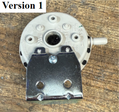
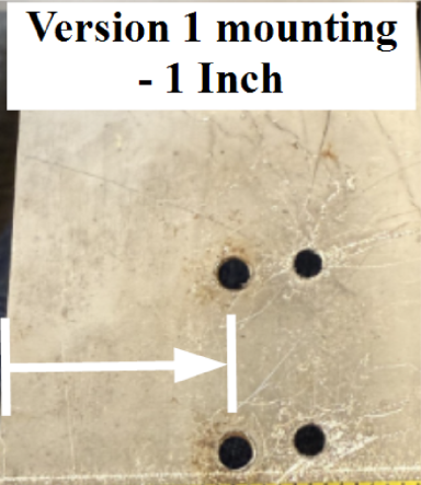
When using a Version 1 switch to replace a Version 2 or older version 1 (skinnier), you may need to remount the switch. If the nozzle does not align with heat shroud to properly mount or any interference with module, measure 1 inch from left and mount switch appropriately.
|
|
-
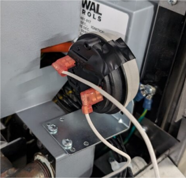
Attach the tube to the nozzle of the switch and zip tie.
-
Mount switch using screws (provided).
-
Rewire switch.
-
Attach the tube to the nozzle of the switch and zip tie.
-
Rewire switch.
-
Mount switch using screws (provided).
NOTE: Rewiring the switch terminals may be required to change them from spade to flag terminals (provided) to not interfere with the display control speaker when placed back up.
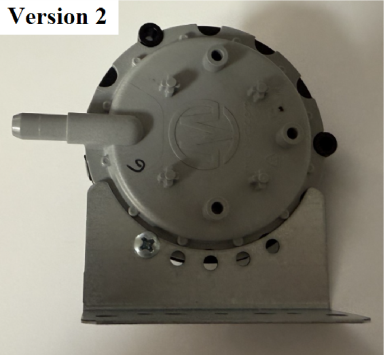
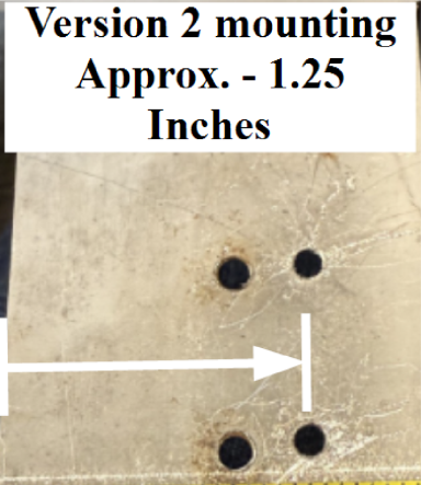
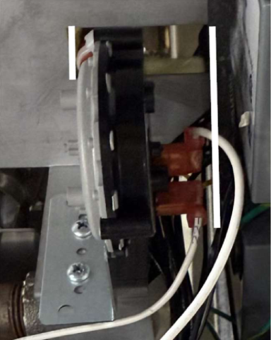
When using a Version 2 switch to replace a Version 1 or older version 1 (skinnier), the switch may need to be remounted. If the nozzle does not align with heat shroud to properly mount or any interference with module, measure approximately 1.25 inches from left and mount switch appropriately.
|
|
NOTE: Rewiring the switch terminals may be required to change them from spade to flag terminals (provided) to not interface with the ignition module. Notice, the wiring is on the opposite side of the version 1 switch.