Bulk Oil System Sequence of Operation
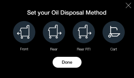
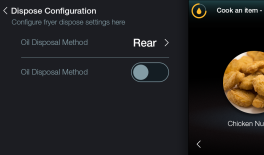
Bulk Oil Dispose
Control Configuration
|
|
|
Prompts
Bulk dispose sequences are user initiated through the F5 control panel manually. The F5 control system has no provision for automatic prompting of oil dispose sequences. During the on-screen bulk dispose control prompts the user is directed to drain used oil to the filter pan. At this time, the filter pan should remain inserted through the bulk dispose sequence.
Filter Pan Switch
After the user initiates a cart dispose cycle, the F5 control system first checks to verify the filter pan is in place. Filter pan position is confirmed through a circuit from the OMS PCB through a normally open magnetic proximity switch and back to the OMS PCB. A 12 volt DC signal is sent from the OMS PCB to the magnetic proximity switch. With the filter pan fully inserted, the magnetic proximity switch is actuated closed by the pan's magnet, and the 12 volt DC signal returns to the OMS. If the filter pan is not fully inserted, the magnetic proximity switch is in its normally open state and the 12 volt DC signal does not return to the OMS. The filter pan switch circuit must be closed before the dispose sequence can progress to the drain step.
-
Normally open magnetic proximity switch
-
Filter pan switch is actuated closed with pan inserted
Filter Pan
Collecting drained oil to be disposed is handled by the filter pan. As oil flows down through the gravity drain system it is first collected for by the dispose cart before being sent to the bulk dispose tank. The filter pan will collect all oil to be disposed from a desired vat.
Selector Valve
Orientation of the selector valve to the vat being disposed occurs as the first dispose action. By first rotating the selector valve to the proper vat position this allows for an oil line purge step later in the dispose sequence. The selector valve is a rotary valve with a fixed body and inner spool that rotates. Rotation and positioning of the selector valve inner spool is provided by a motor/encoder assembly. To rotate the selector valve spool a 24 volt DC signal is sent from the OMS PCB to the selector valve motor. As the selector valve motor rotates, a pulsing 5 volt DC encoder position signal is returned to the OMS. Once the desired selector valve position is confirmed the OMS PCB removes the 24 volt DC signal, and the motor stops rotating. The selector valve motor will rotate in either direction to achieve the desired position with shortest travel. The OMS PCB reverses 24 volt DC rotation signal polarity to change motor direction.
Drain
During the drain stage, a 24 volt DC signal is sent from the OMS PCB to the drain valve actuator which causes the valve to open. With the drain valve open, used oil to be disposed flows by gravity from the vat to the drain trough and then to the filter pan. A 24 volt DC signal in the opposite polarity is sent from the OMS PCB to the drain valve actuator to close the valve after the Dispose sequence. Mechanical limit switches internal to the drain valve actuator provide position feedback to stop rotation when opening or closing.
-
24 volt DC signal to open drain valve
-
Opposite polarity 24 volt DC signal to close drain valve
Purge
Clearing of old oil in the vat's plumbing is performed by the purge stage. The drain valve remains open and while the user is purging oil and a line voltage AC single-phase signal is sent from the OMS PCB to the ATO pump. New cold oil is then drawn from the ATO reservoir (JIB) and is sent through the selector valve return, plumbing lines, and check valve. Once old oil pushed through the lines and new oil enters the vat, the purge pump may be stopped. Excess oil from the purge stage may be directed toward the open drain. After completion of the purge stage, the drain valve will close to allow for filling of the vat with new oil.
Selector Valve
Orientation of the selector valve to the bulk dispose position is the next dispose action. By rotating the selector valve to the bulk dispose position this provides a flow path for disposed oil to leave the fryer and enter the bulk oil system.
Dispose Tank Level
Before drained oil is sent to the dispose tank, the F5 control system checks to ensure the dispose tank is not full. Dispose tank level is confirmed through a circuit from the OMS PCB through a normally open liquid level switch and back to the OMS PCB. A 24 volt AC signal is sent from the OMS PCB to the dispose tank level switch. With the dispose tank level below full the level switch remains open and the 24 volt AC signal does not return to the OMS PCB. If the dispose tank level is full, the level switch is closed and the 24 volt AC signal returns to the OMS. The dispose tank level switch circuit must be open before the dispose sequence can progress to the next step.
Filter Pump/Motor
Transporting disposed oil from the filter pan to the bulk dispose tank is performed by the filter pump which is moved by a line voltage AC, single-phase, 1/2 HP (0.37 kW) electric motor. Line voltage is continually supplied to the OMS PCB for the filter pump motor and ATO pump. When the F5 control system energizes the filter pump motor, an OMS PCB mounted relay closes, sending single-phase line voltage to the motor.
NOTE - Single-phase electric motors rotate in one direction only. The filter pump motor rotates clockwise (CW) as viewed from the motor's rear face with reset button. If viewing the filter pump motor from the output shaft end, rotation will be in the counterclockwise or anticlockwise (CCW or ACW) direction.
The filter pump input shaft connects directly to the motor shaft and the pump body is mounted to the motor hub, secured with three (3) set screws. Orientation of the filter pump may be changed by loosening the set screws and rotating the pump body as needed. Inlet and outlet port sizes are SAE-12 with a required fitting o-ring seal, washer, and jam nut. The pump inlet side includes a 1/4 NPT plug for oil priming or inspection as needed. Oil flow is generated by PTFE rollers that are spun by the pump rotor that is permanently press fit to the input shaft. Filter pump outlet flow is a nominal 8 (US) gallons per minute (GPM) or 30 liters per minute (L/min).
NOTE - The filter pump body and cap have ribs cast as part their material and should always align on the same side. Ensure proper pump cap alignment after removal and reinstall.
NOTE - Never separate the filter pump rotor and body. Separating the rotor and body will cause permanent damage to the filter pump's non-serviceable shaft seal and require a complete pump replacement.
NOTE - Only use the filter pump to transport cooking oil. Using the filter pump to move water, cleaning solution, or other non-food rated material will cause contamination and/or permanent damage to the pump.
Dispose Connection
A flexible dispose oil line external to the F5 fryer connects to the bulk oil system plumbing. Depending on bulk oil system type and fryer configuration, the flexible dispose oil line will be either supplied by Henny Penny or the bulk oil system vendor. The Henny Penny provided bulk oil dispose line has a female quick disconnect coupling end that must be mated properly to the bulk oil plumbing before disposed oil will flow. A vendor supplied bulk dispose hose would have a threaded connection to the fryer rear.
Vendor Bulk Dispose Switch
Some bulk oil system vendors provide a dispose switch that may be mounted to the F5 fryer and connected to the OMS PCB. The bulk oil dispose switch when engaged provides a method to energize the fryer filter pump to send drained oil to the bulk dispose tank. A 24 volt DC signal is sent by the OMS PCB to the bulk dispose switch. When the switch is closed and 24 volts DC returns to the OMS PCB, then the filter pump is energized to transfer drained oil to the bulk dispose tank. When the user releases the bulk dispose switch, the filter pump will stop.
-
24 volt DC signal from OMS to normally open switch
-
Bulk dispose switch is actuated closed by user
-
24 volt DC signal returns to OMS PCB and filter pump energized
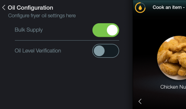
Bulk Oil Supply
Control Configuration
Supply Connection
A flexible supply oil line external to the F5 fryer connects to the bulk oil system plumbing. Depending on bulk oil system type and fryer configuration, the flexible supply oil line will be either supplied by Henny Penny or the bulk oil system vendor. Vendor supplied bulk oil supply hose would have a threaded connection to the fryer rear.
Prompts
Bulk supply or fill sequences are user initiated through the F5 control panel manually. The F5 control system has no provision for automatic prompting of bulk oil fill sequences. During the on-screen bulk fill control prompts the user is provided a choice whether to fill a vat manually or via the bulk system.
Selector Valve
Orientation of the selector valve to the vat or ATO reservoir (JIB) being filled occurs as the first bulk supply action. By first rotating the selector valve to the proper vat or ATO reservoir fill position this allows for an open flow path. The selector valve is a rotary valve with a fixed body and inner spool that rotates. Rotation and positioning of the selector valve inner spool is provided by a motor/encoder assembly. To rotate the selector valve spool a 24 volt DC signal is sent from the OMS PCB to the selector valve motor. As the selector valve motor rotates, a pulsing 5 volt DC encoder position signal is returned to the OMS. Once the desired selector valve position is confirmed the OMS PCB removes the 24 volt DC signal, and the motor stops rotating. The selector valve motor will rotate in either direction to achieve the desired position with shortest travel. The OMS PCB reverses 24 volt DC rotation signal polarity to change motor direction.
External Bulk Oil Supply Pump
A bulk oil supply system is equipped with a pump provided by the vendor and external to the fryer. When energized, the bulk oil supply pump sends new oil to the F5 fryer for filling a vat or the ATO reservoir (JIB). When a user wants to fill a vat or ATO reservoir with new oil, the bulk oil supply pump is activated by a 24 volt AC signal from the OMS PCB to the external pump relay. When the bulk oil supply pump relay closes, the pump is energized.
-
24 volt AC signal from OMS to bulk oil supply pump relay
-
Bulk oil pump energizes
Filling Vat
Filling of a vat from bulk requires the bulk supply pump to be energized to move oil from the tank. Oil from the bulk supply pump passes through a one-way return check valve before entering the vat. The return check valve requires an oil pressure of 2 PSI (138 mbar) to open and allow oil flow. Otherwise, the return check valve remains closed to prevent oil back flow through the fryer plumbing. The F5 control system does not detect vat oil level when filled from bulk. The user must stop the bulk oil fill sequence once the hot or cold vat level line is reached.
-
Return check valve requires 2 PSI (138 mbar)
-
OMS PCB 24 volt AC signal to bulk oil supply pump motor stops when user ends fill request to control
Filling ATO Reservoir (JIB)
Filling of the ATO reservoir (JIB) requires the bulk supply pump to be energized to move oil from the tank. Oil from the bulk supply pump passes through the selector valve and then on to the reservoir. The ATO fill line will meet at a tee fitting that connects to the line for oil being drawn from the reservoir. Between the tee fitting and the ATO reservoir the single oil line allows for two-way flow to and from the reservoir.
-
OMS PCB 24 volt AC signal to bulk oil supply pump motor stops when user ends fill request to control
Vendor Bulk Fill Switch
Some bulk oil system vendors provide a fill switch that may be mounted to the F5 fryer and connected to the OMS PCB. The bulk oil fill switch when engaged provides a method to energize the bulk supply pump to send new oil to the ATO reservoir (JIB). A 24 volt DC signal is sent by the OMS PCB to the bulk fill switch. When the switch is closed and 24 volts DC returns to the OMS PCB, then a 24 volt AC signal is sent from the OMS to the bulk supply pump relay. The bulk supply pump is energized to transfer new oil to the ATO reservoir. When the user releases the bulk fill switch, the supply pump will stop.
-
24 volt DC signal from OMS to normally open switch
-
Bulk fill switch is actuated closed by user
-
24 volt DC signal returns to OMS PCB and bulk supply pump signal sent to relay
Related Content
ATO System Sequence of Operation
ATO System Theory of Operation
Bulk Oil System Theory of Operation
Cart Dispose System Sequence of Operation
Cart Dispose System Theory of Operation
Electric Heat Sequence of Operation
Electric Heat Theory of Operation
Filtering Sequence of Operation
Power Distribution Board (PCB) Theory of Operation
Power Modulation Unit (PMU) High Limit Theory of Operation
Reference
OFE 51X Software without Connectivity