OFE 51X Wiring Diagrams
208 – 240V Wiring diagrams labeled on unit
174492 F Non-interlock, 208-240V, 3+G, 14kW Label
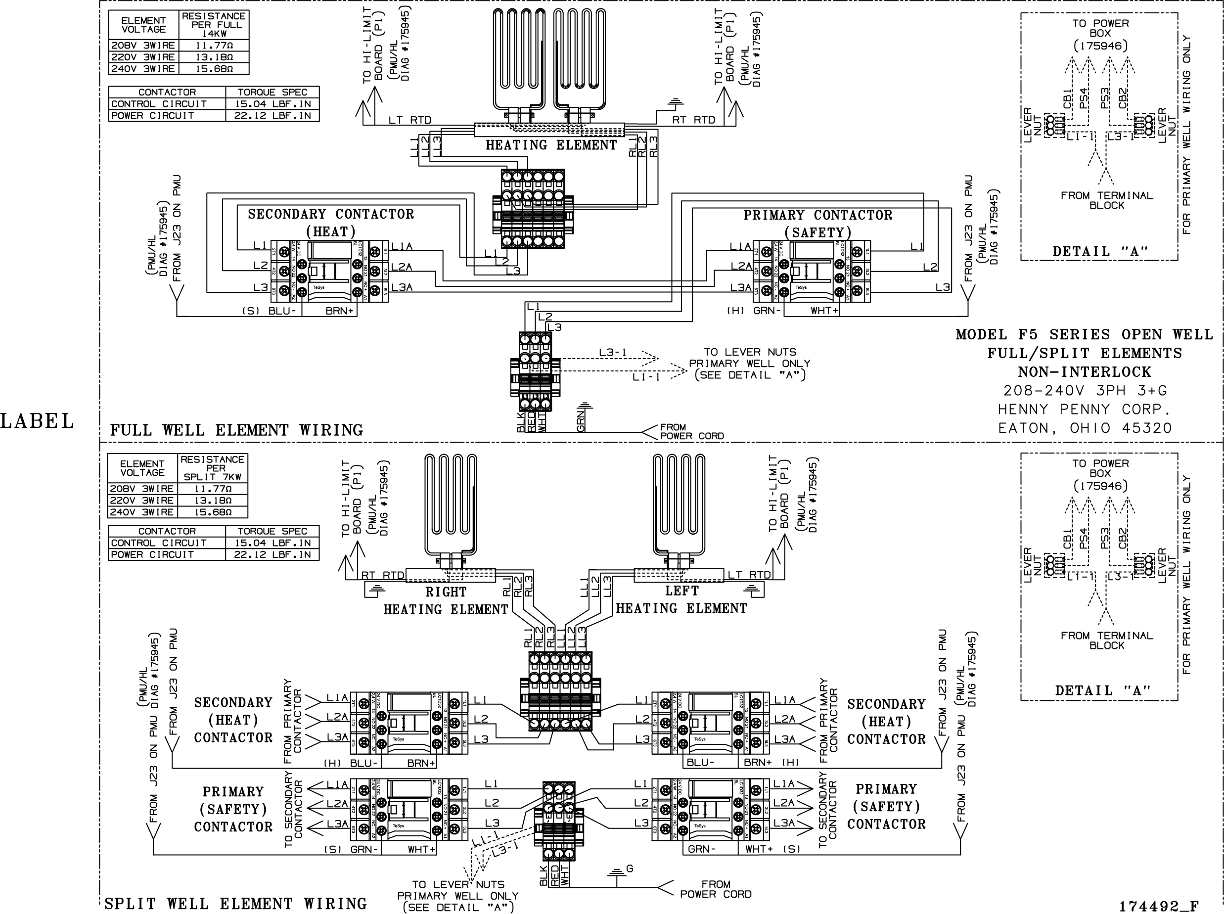
175646 G Non-interlock, 208-240V, 3+G, 17kW Label
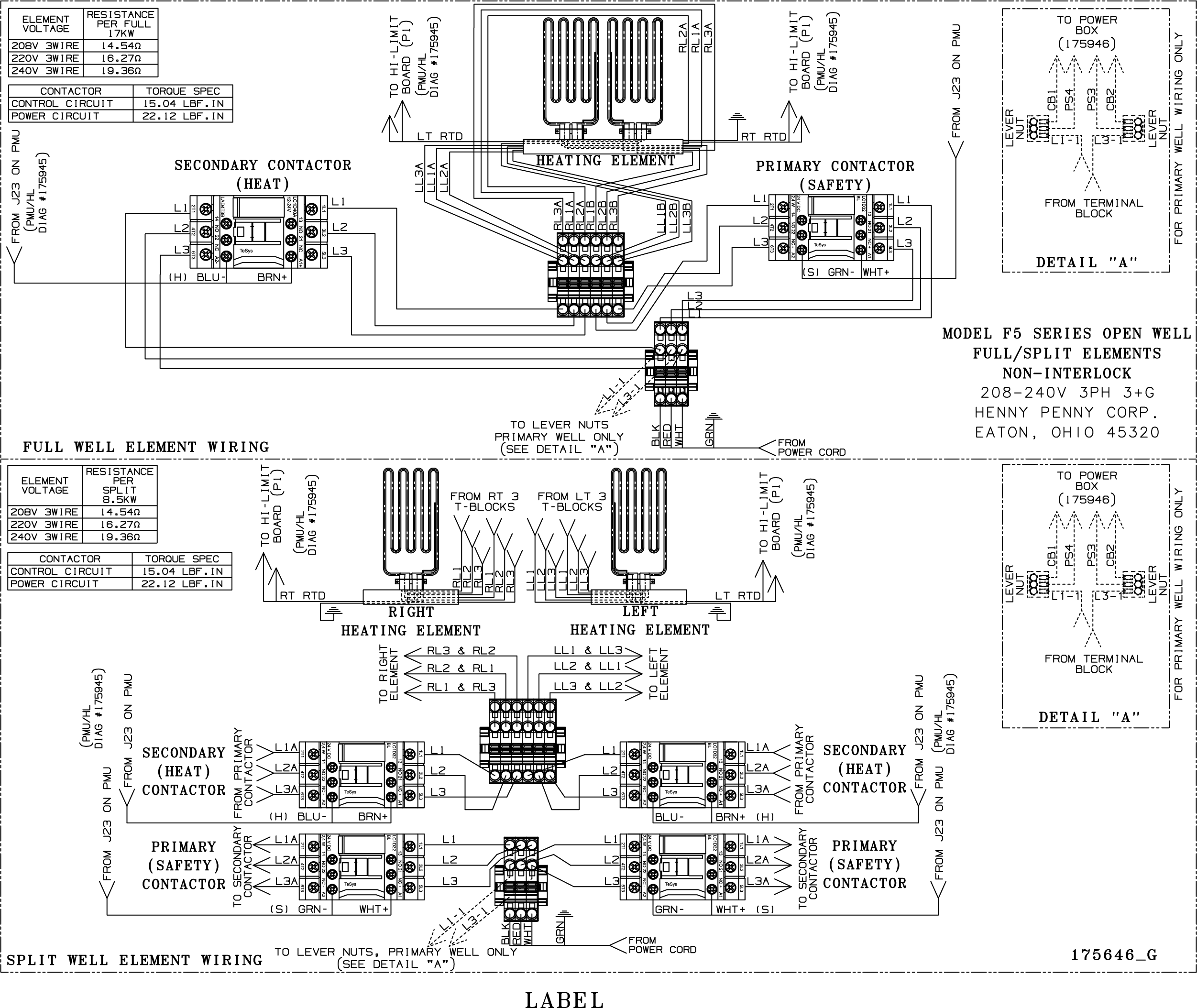
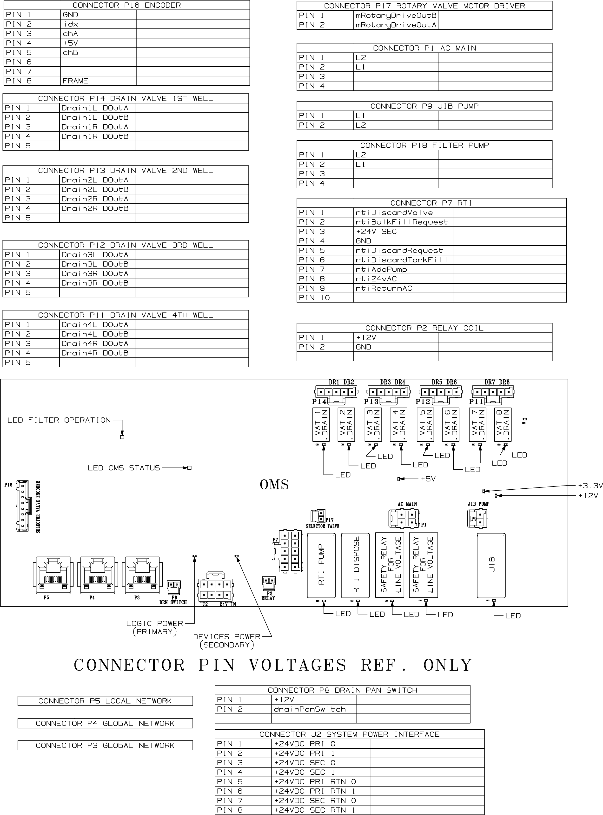
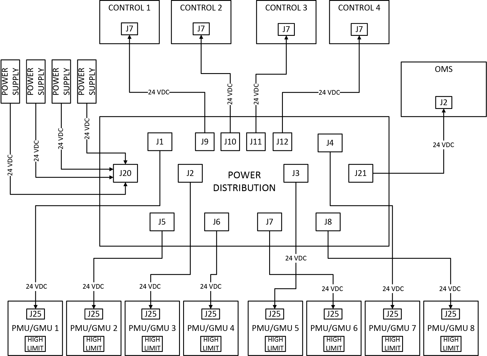
175924 F OMS Power Distribution Label
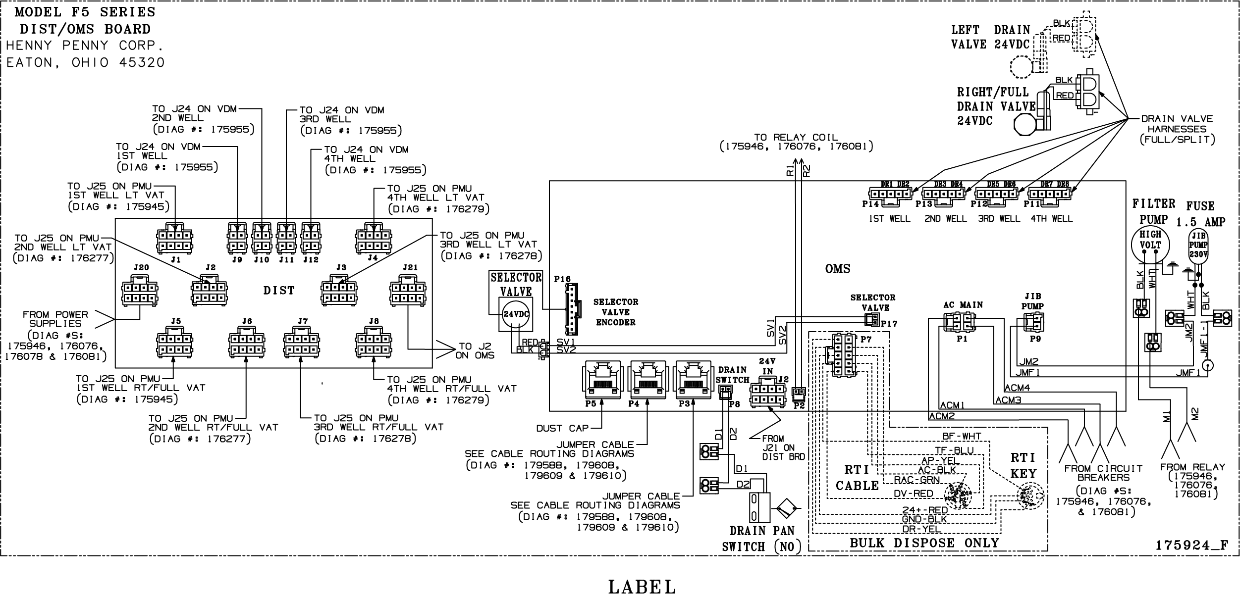
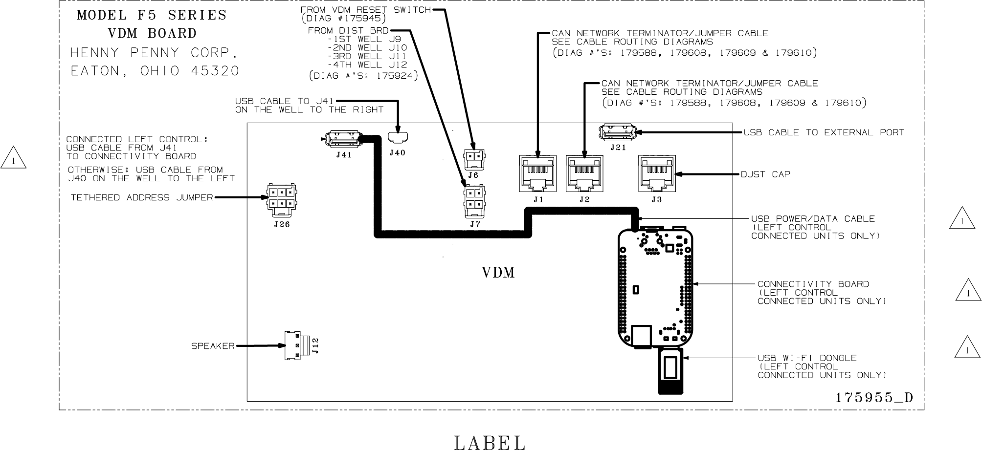
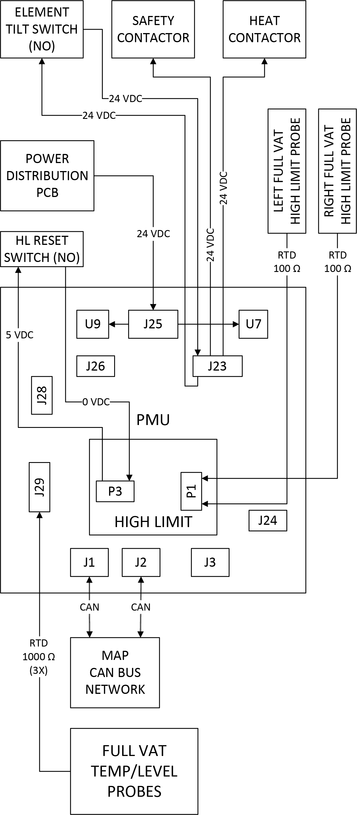
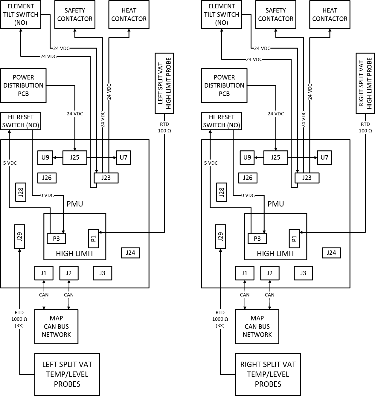
175945 C PMU/ High Limit Board Label
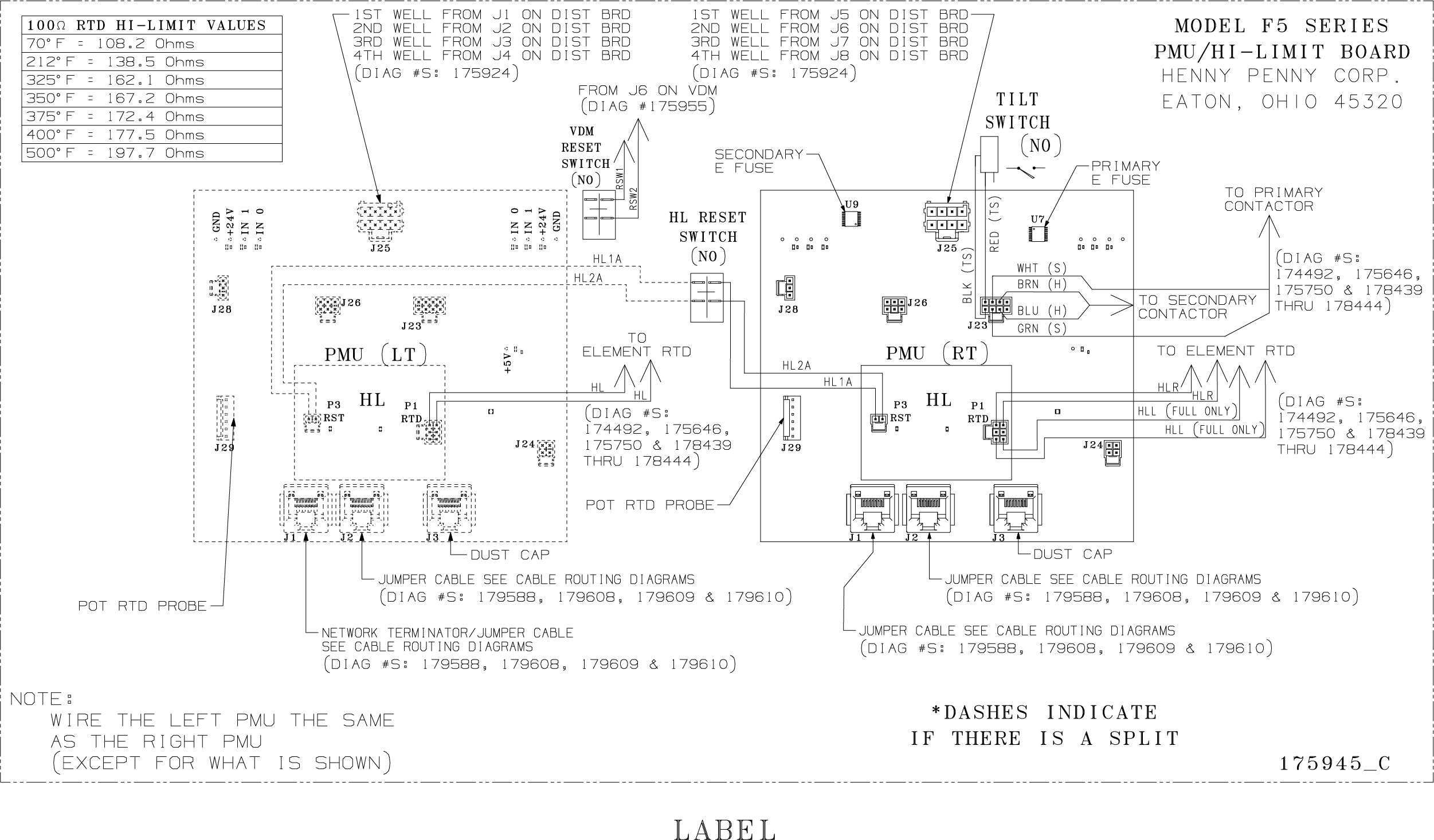
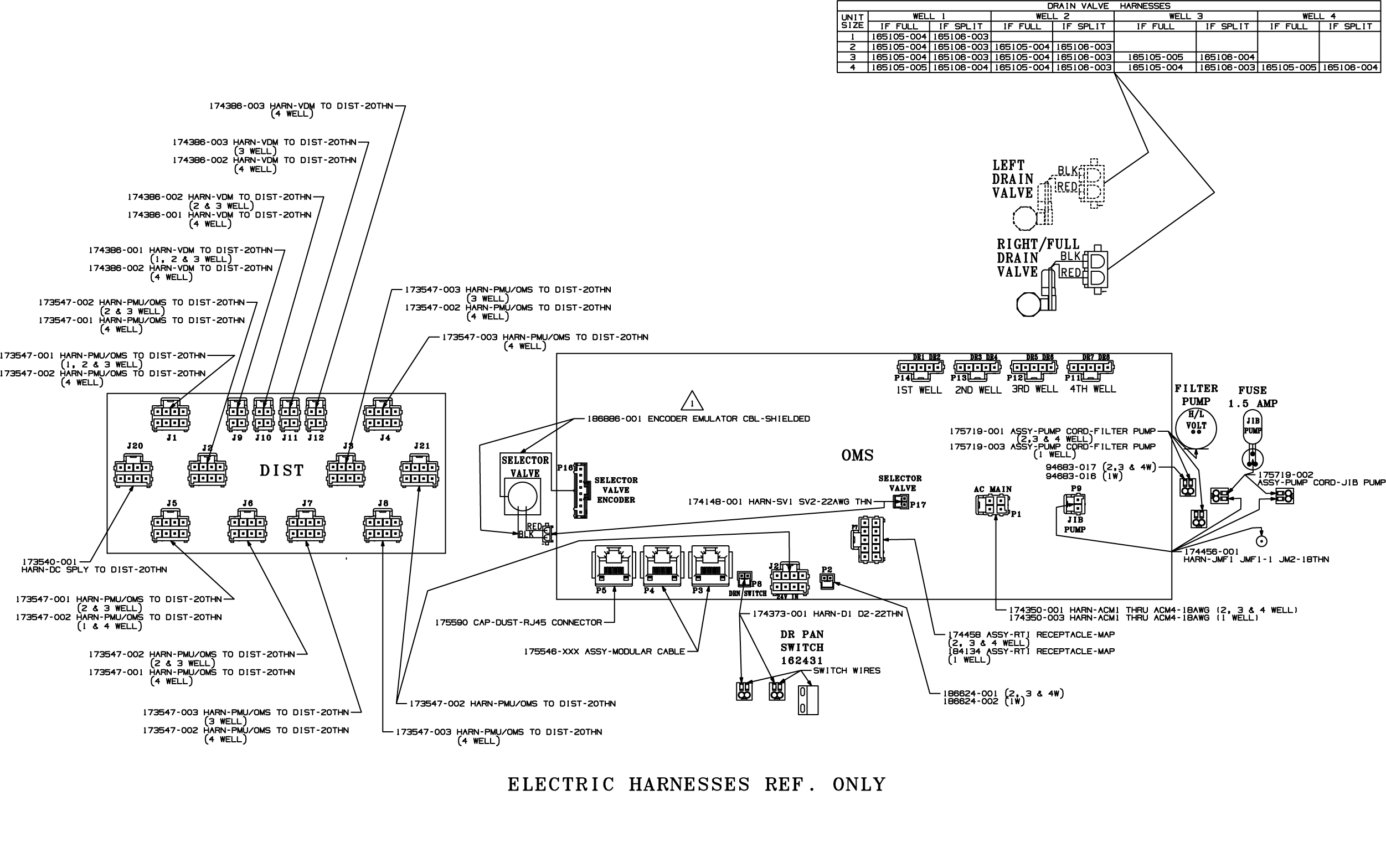
175946 J Non-Interlock Power Box Connector Pin Voltage Diagram
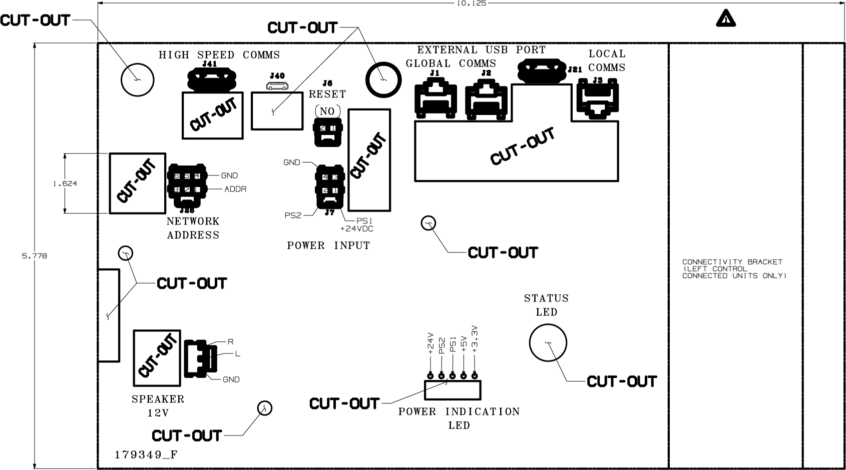
179349 F5 Control Diagram Label
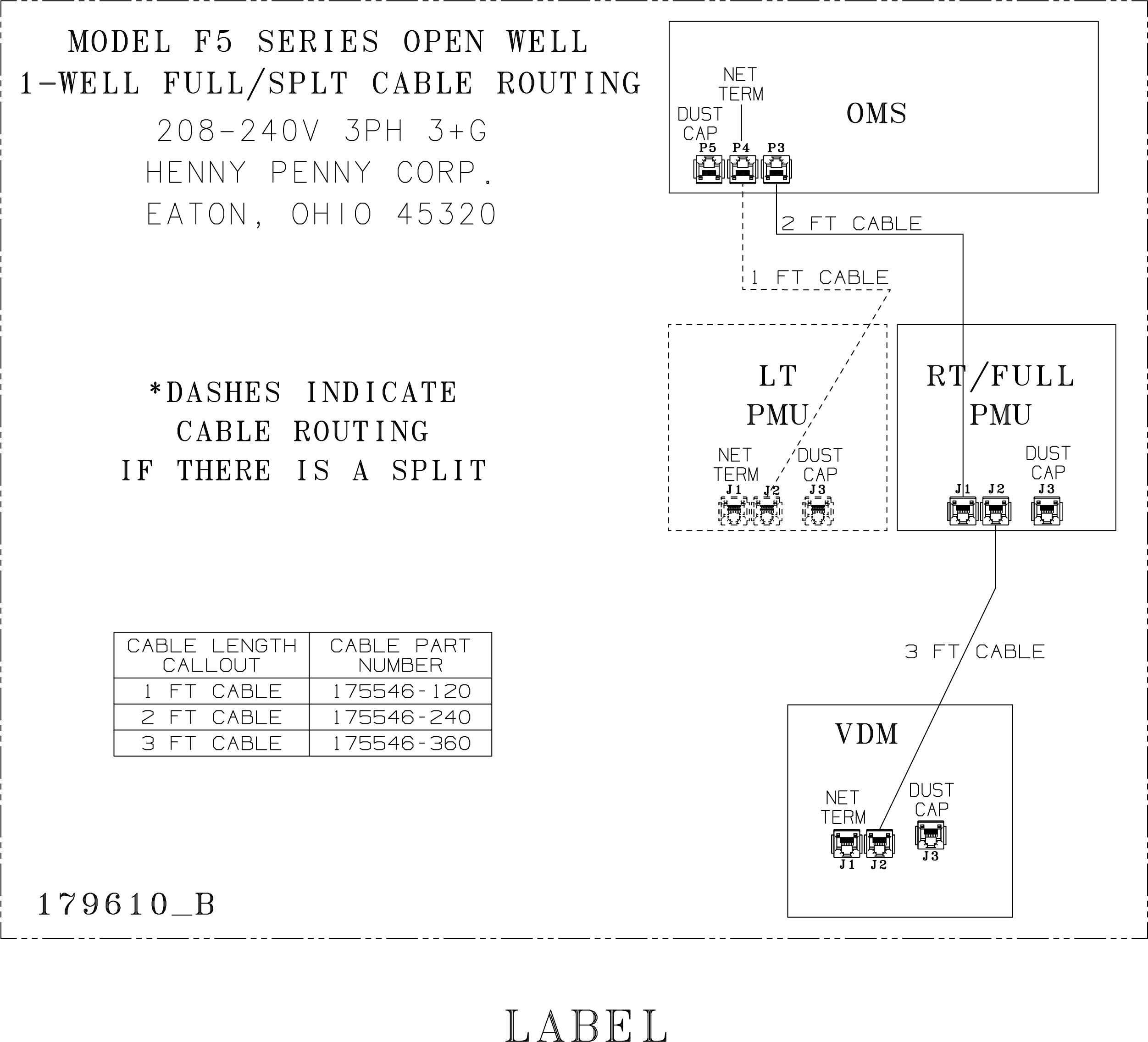
179610 B One Vat Cable Routing Diagram
179609 A Two Vat Cable Routing Diagram
179608 A Three Vat Cable Routing Diagram
179588 A Four Vat Cable Routing Diagram
380 - 415V 3NG Wiring diagrams labeled on unit
175750 F Non-interlock, 380-415V, 3pH, 3NG Label
175924 F OMS Power Distribution Label
175945 C PMU/ High Limit Board Label
175946 J Non-Interlock Power Box Connector Pin Voltage Diagram
179349 F5 Control Diagram Label
179610 B One Vat Cable Routing Diagram
179609 A Two Vat Cable Routing Diagram
179608 A Three Vat Cable Routing Diagram
179588 A Four Vat Cable Routing Diagram
Pin Voltage Diagrams
175924 F OMS Power Connector Pin Voltage Diagram
175924 F OMS Power Distribution Connector Pin Voltage Diagram
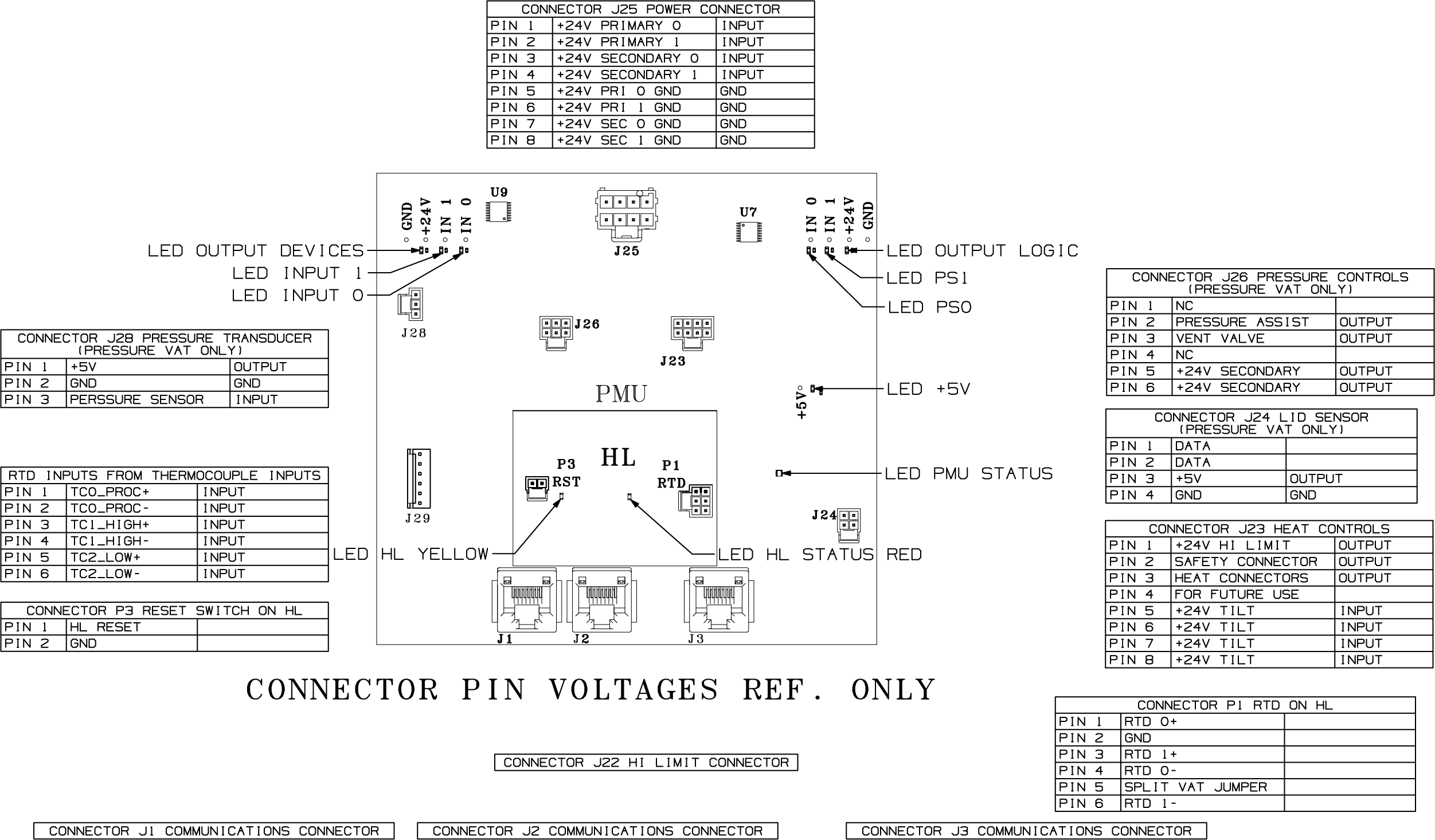
175945 C PMU/ High Limit Board Connector Pin Voltage Diagram
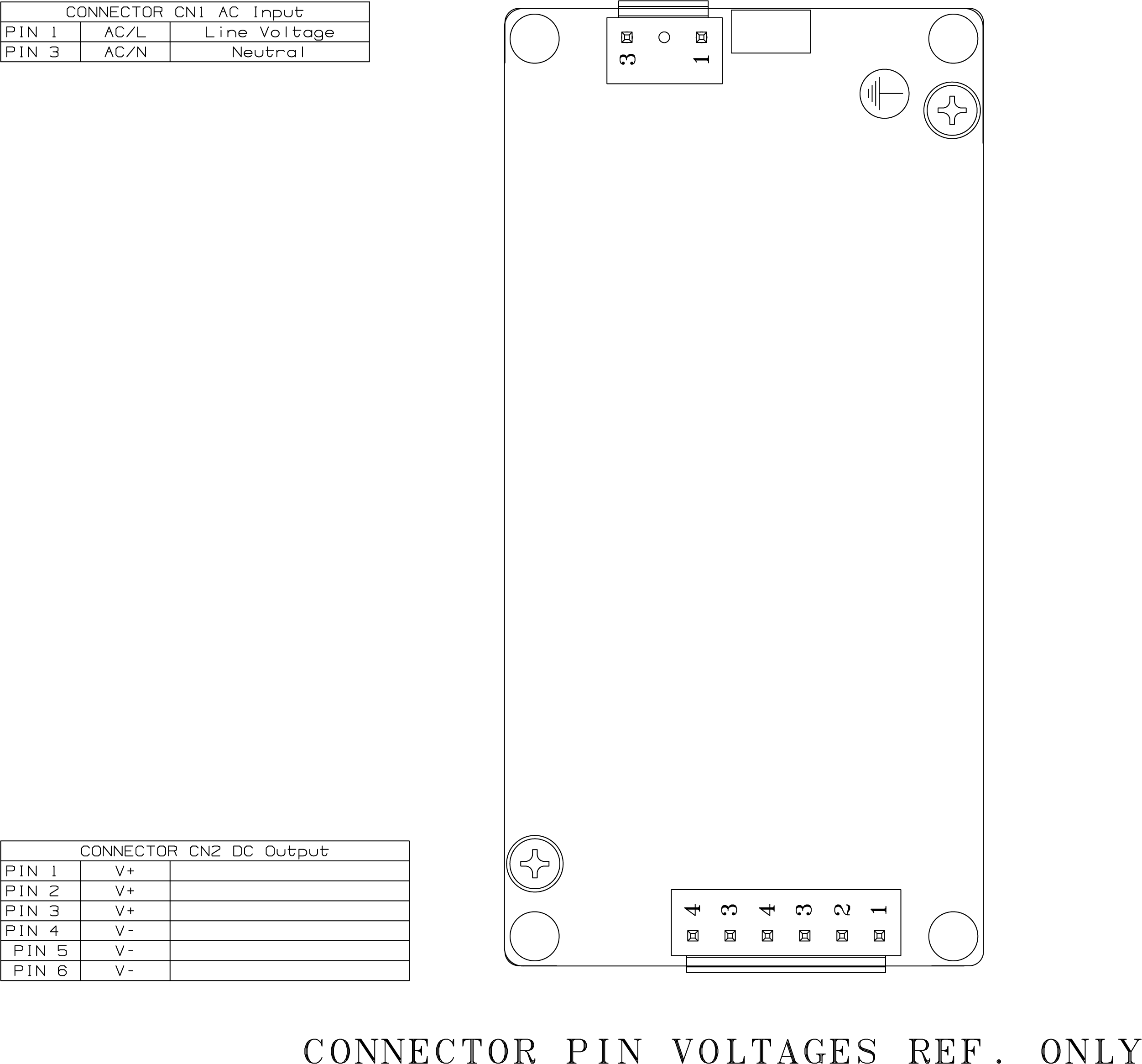
175946 J Non-Interlock Power Box Connector Pin Voltage Diagram
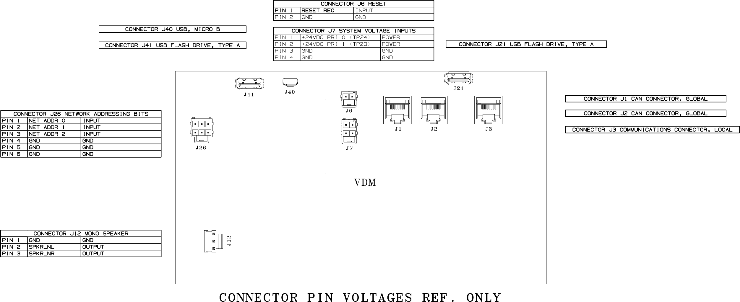
175955 C VDM Board Connector Pin Voltages Diagram
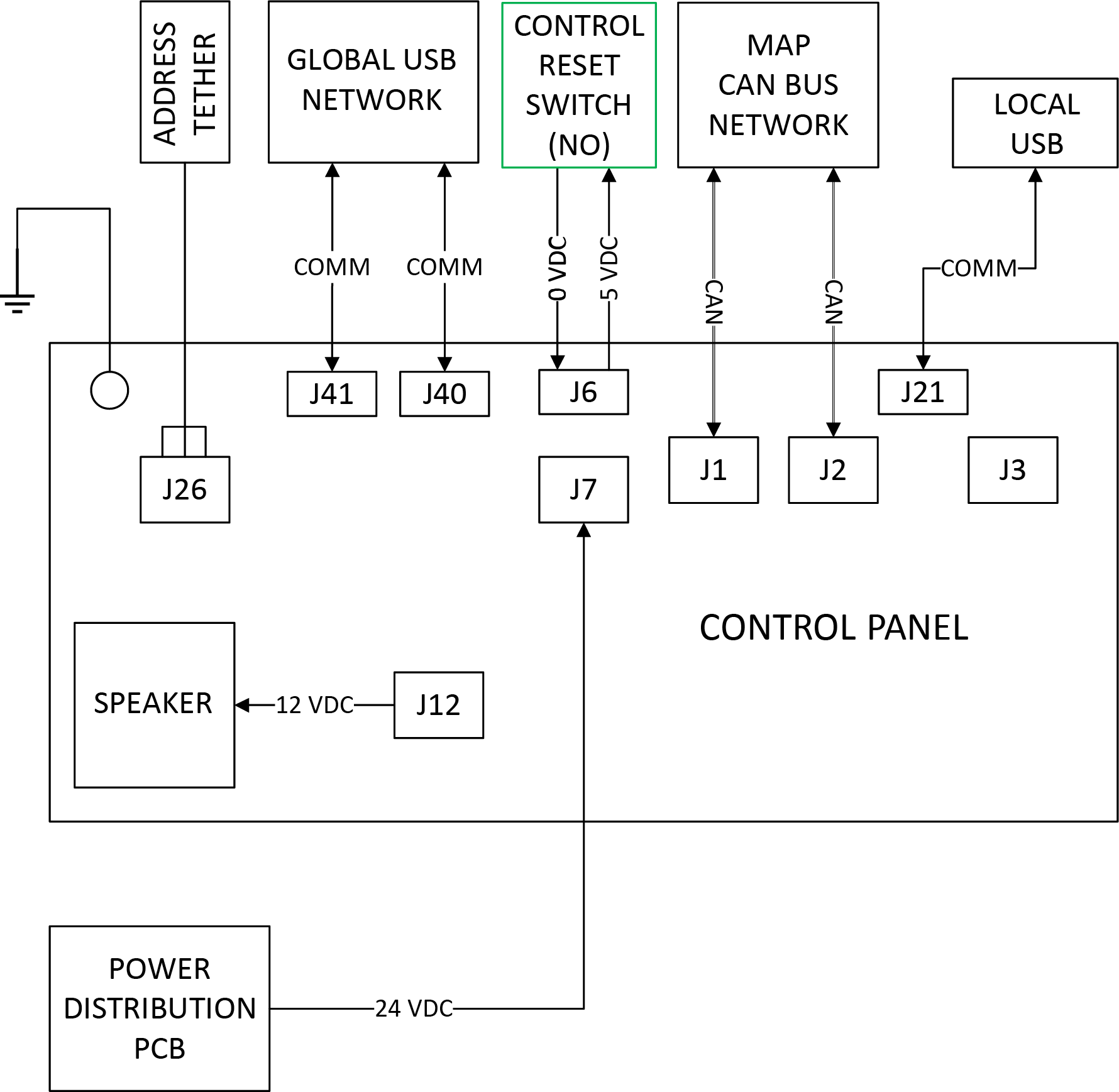
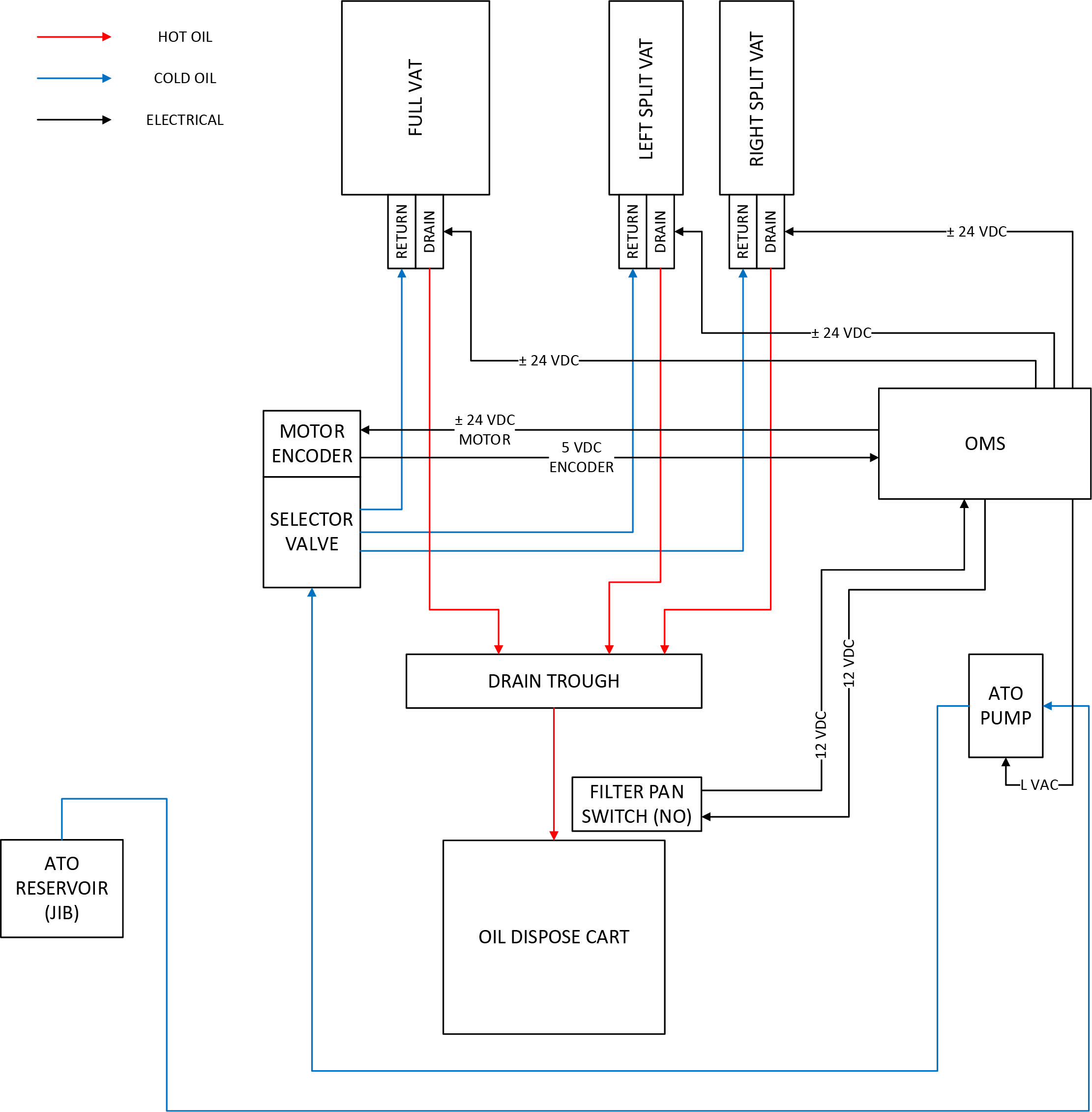
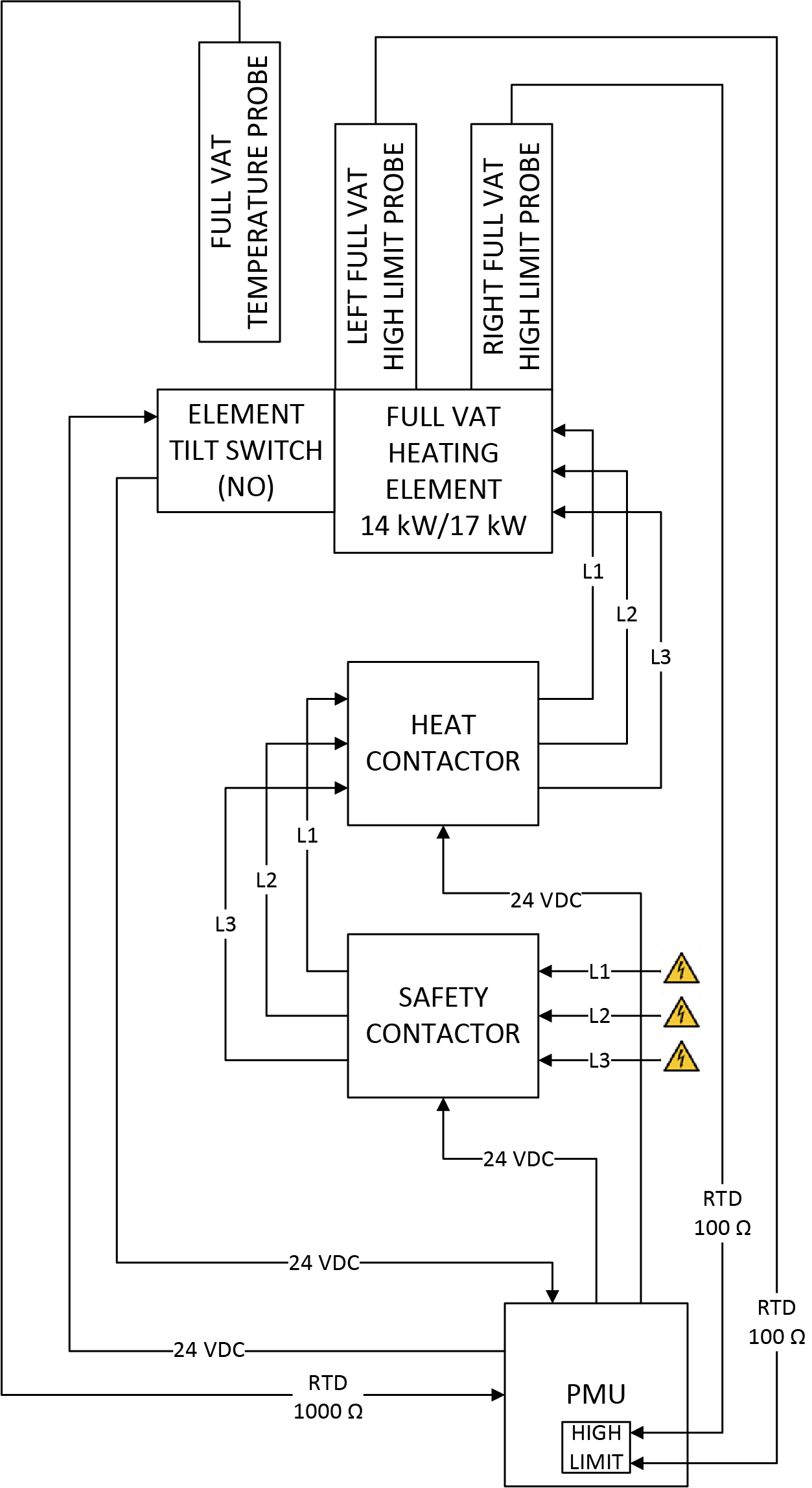
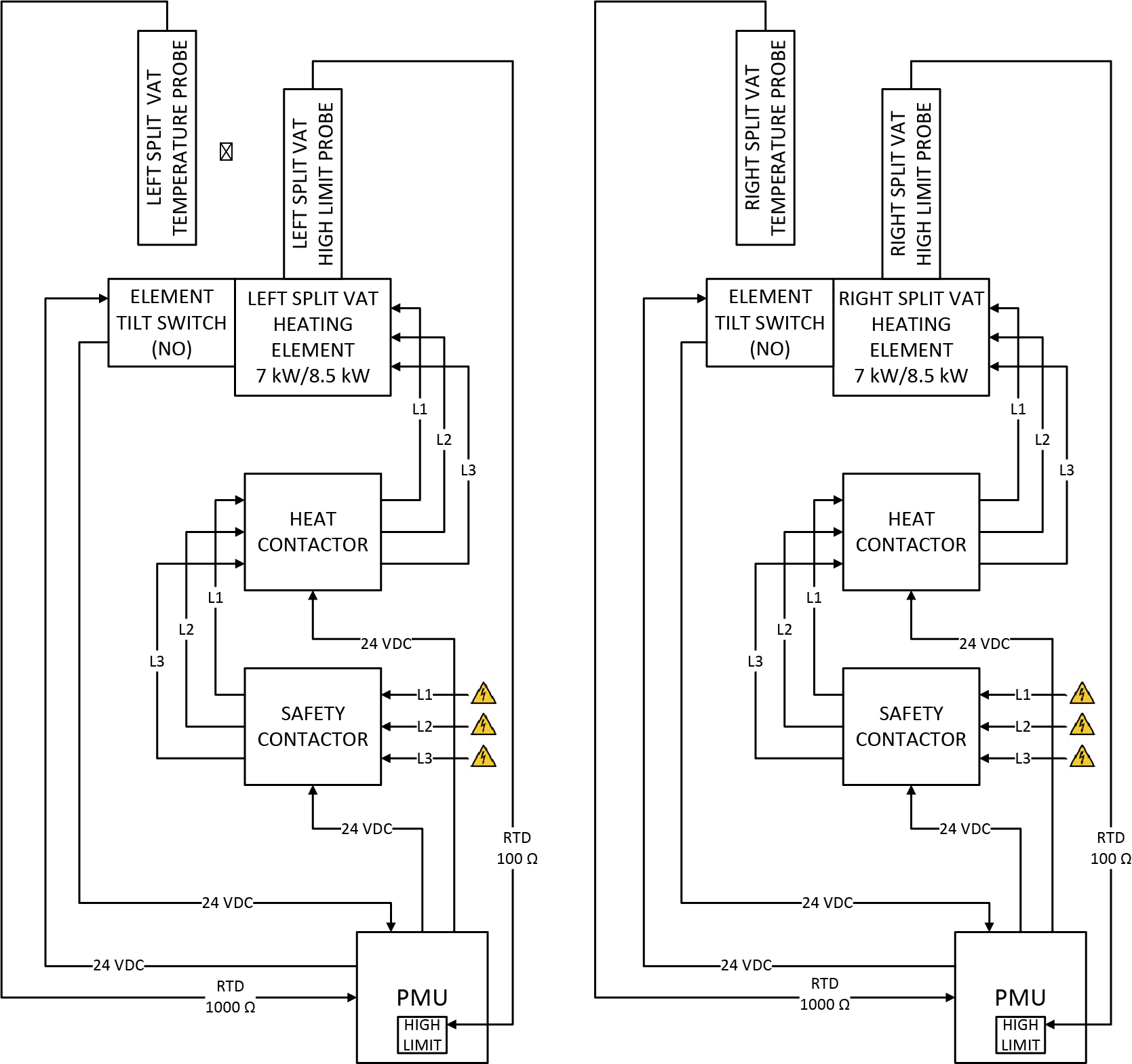
Block Diagrams
Electric Heat System Block Diagram Full Vat
Electric Heat System Block Diagram Split Vat
Power Distribution PCB Block Diagram
Related Content
Installing the OFE 51X Open Fryer
Operating the OFE 51X Open Fryer
Training on the OFE 51X Open Fryer
Programming the OFE 51X Open Fryer
Troubleshooting the OFE 51X Open Fryer
Information on the OFE 51X Open Fryer
How to Enable Network Connectivity
Discarding Oil Using Front Dispose
Discarding Oil Using Rear Dispose
Discarding Oil Using Rear RTI Dispose
Discarding Oil Using Cart Dispose
Cleaning the Filter Pan Assembly
Replacing the Filter Pan Lid Gasket
Tighten Heat Probe and Element Spreader Bars
Managing Over the Air Connectivity Software Updates
Changing from a Dedicated Display to a Multi-Product Display
Updating Connectivity Software
ATO System Sequence of Operation
ATO System Theory of Operation
Bulk Oil System Theory of Operation
Cart Dispose System Sequence of Operation
Cart Dispose System Theory of Operation
Electric Heat Sequence of Operation
Electric Heat Theory of Operation
Filtering Sequence of Operation
Power Distribution Board (PCB) Theory of Operation
Power Modulation Unit (PMU) High Limit Theory of Operation
Bulk Oil System Sequence of Operation
Troubleshooting the Access Point Connection
Troubleshooting the Cloud Connection
Troubleshooting the User License Agreement (ULA)
Troubleshooting the IP Address
Troubleshooting the Radio (Dongle)
Troubleshooting Radio Software Setup
Troubleshooting Signal Strength
Troubleshooting a Blank Display
Troubleshooting an E-5 Error Oil Too Hot
Troubleshooting an E-6 Error Main or Temperature Probe
Troubleshooting an E-10 High Limit Error
Troubleshooting an E-21 Error Recovery Fault
Troubleshooting an E-22 Error No Heat
Troubleshooting an E-31 Error Elements Up
Troubleshooting the Check JIB Message
Selector Valve Port Configurations
Replacing the Selector Valve Motor
Replacing the Port Selector Valve Assembly
Troubleshooting a Drain Pan Switch Failure
Troubleshooting a Change Pad Reminder XX hrs. Error
Troubleshooting an E-82D Selector Valve Error
CE Filter Motor Cover Retrofit
Bulk Dispose and Fill Retrofit
Retrofitting Adjustable Filter Pan Guide Rail
Reference
OFE 51X Software (without Connectivity)