OMS Theory of Operation
OMS Purpose
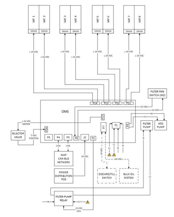
Tracking of oil movement along with filter queuing and logic is managed by the OMS PCB. Primarily, the OMS is powered by 24 volts DC from the Power Distribution PCB. Additionally, line voltage is supplied to the OMS from the power switch and terminal blocks. Incoming to the OMS are selector valve encoder position and bulk oil system signals. Outputs of the OMS are 24 volts DC to the selector valve motor and drain valve actuators for all vats. Additional OMS outputs are line voltage to energize the filter and ATO pumps. A filter pan magnetic proximity switch circuit is monitored by the OMS and is closed with the pan in place or open with the pan out.
-
Tracking of oil movement, filter queuing and logic
-
Incoming line voltage from push button circuit breakers for filter and ATO pumps
-
Control of all fryer pumps and valves
-
Incoming selector valve encoder position signals
-
Filter pan magnetic proximity switch circuit
-
Output and Input signals for optional bulk oil systems
OMS Block Diagram:
Related Content
ATO System Sequence of Operation
ATO System Theory of Operation
Bulk Oil System Sequence of Operation
Bulk Oil System Theory of Operation
Cart Dispose System Sequence of Operation
Cart Dispose System Theory of Operation
Touchscreen Control MAP Theory of Operation
Filtering Sequence of Operation
Gas Heat System Sequence of Operation
Gas Heat System Theory of Operation
GMU Hi Limit Theory of Operation
Power Distribution Board (PCB) Theory of Operation
Power Modulation Unit (PMU) High Limit Theory of Operation
Reference