Replacing the Temperature Level Probe

|
To avoid electrical shock or property damage, move the power switch to OFF and disconnect power. |
-
Ensure the oil is drained from the vat and filter pan.
-
Remove the filter pan and set aside.
-
Remove the power from the fryer.
-
Remove the reserve oil tank and set aside.
-
Note how and where the old temperature probe protrudes through the front side of the vat.
-
Lower or remove the front control panel as needed for access.
-
Remove front, left or right-side panels as needed for access.
-
Disconnect the temperature probe wire lead, which is located behind the control panel.
-
Remove the nut connecting the temperature probe to the vat.
-
Apply white Loctite to the threads of the compression nut on the new temperature probe and then insert through opening.
-
Tighten the temperature probe compression nut by hand to snug (zero torque), and then add 1/4 half turn with a wrench. Do not overtighten.
-
Connect the wire lead.
-
Install the filter pan, reserve oil tank.
-
Reconnect the power.
-
Add oil to the vat and then run a filter cycle while checking for leaks.
-
If leaks are discovered, repair as necessary.
-
Test the temperature probe to ensure it works properly.
-
Replace all the panels.
-
Use an adjustable wrench to access the flex lines.
Removing the Old Heating Element Assembly
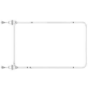
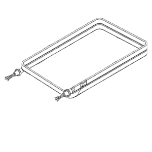
The heating element assembly, which consists of two of the same heating elements bound together by spreader bars must be removed as an assembly from the vat. When replacing one or both elements the entire assembly must be removed.
-
Note how and where the heating elements and temperature probes protrude through the front side of the vat.
-
Loosen all four spreader bar sets but do not remove the screws completely.
-
Disconnect all the thermocouple probe wire leads, which are located behind the control panel.
-
Remove each of the compression nuts connecting the thermocouple probes to the vat.
-
Disconnect the upper and lower heating element wire leads from both contactors. The contactors are located on the inside shroud behind the control panel.
-
Remove each of the nuts connecting the heating elements to the vat.
-
Remove the O-ring that seals the element to the vat.
-
Lift up the rear of the heating element assembly and remove from the vat.
-
Place the heating element assembly on a flat sturdy work surface and disassemble.
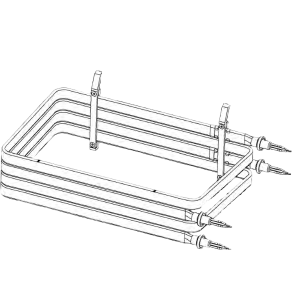
Bench Building the New Heating Element Assembly
-
Place both heating elements on a flat, sturdy work surface.
-
Draw a mark on the left front side of the upper heating element five inches rear of the connector flange.
-
Draw a mark on the left and right side of the upper heating element 3 1/8 inches forward of the rear of the heating element.
-
Draw a mark on the right front side of the upper heating element 4 1/2 inches rear of the connector flange.
-
Draw a mark on the right front side of the upper heating element 4 inches rear of the connector flange.
-
-
Position one high limit clip on the top front right side of both heating elements.
-
Place upper heating element on top of the lower heating element.
-
Position angled spreader and straight spreader over the high limit clips on the front right side of the heating elements.
-
Position angled spreader and straight spreader over the high limit clips on the rear right side mark on the heating element.
-
Insert four Allen screws into the right side spreader bars and to keep them together.
-
Position one angled spreader and one straight spreader on each mark on the left side of the heating element assembly. Ensure not to over tighten the Allen screws. The screws are permanently tightened when the heating element assembly is placed in the vat.
-
Insert four Allen screws into the left side spreader bars and to keep them together.
-
Place four O-rings over the wires onto the four connectors.
-
Label the wires on the upper heating element B and label the wires on the lower heating element A.
Installing the Element
-
Position heating element in the vat at an angle with the front end first.
-
Route wiring through holes in the front of the vat.
-
Place two washers on the threaded end of each heating element connector.
-
Place a nut on the threaded end of each heating element connector securing the heating element assembly to the fry pot.
-
Tighten all four nuts. Apply 32 ft. lbs. of torque.
-
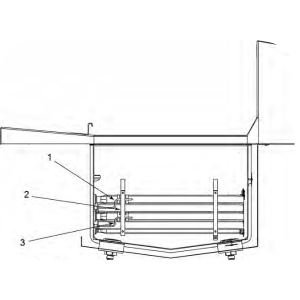
Apply white Loctite to the threads of the compression nut on the thermocouple probe (2). Insert through spreader (3) opening.
-
Apply white Loctite to the threads of the compression nut on the thermocouple probe (2) and insert through spreader (3) opening.
-
Tighten the thermocouples by hand to snug (zero torque) and then add 1/4 to 1/2 half turn with a wrench. Do not overtighten.
-
Tighten both Allen screws(2) on the front right spreader assembly (1) securing the spreader to the heating element assembly (3). Apply 32 in. lbs. of torque.
-
Position rear right spreader bar assembly (4) 3.5 inches from rear vat wall.
-
Tighten Allen screws (5) securing rear right spreader bar assembly (4) to the heating element assembly (3). Apply 32 in. lbs. of torque.

-
Route heat probe (5) through front left spreader bar assembly (3).
-
Position the tip of the heat probe (5) 4 inches from the vat wall (4).
-
Position front left spreader bar assembly (3) 4.250 inches from the vat wall (4).
-
Tighten Allen screws (6) securing front left spreader bar assembly (3) to the heating element assembly (2). Apply 32 in. lbs of torque.
-
Position rear left spreader bar (1) 3.5 inches from rear vat wall (8).
-
Tighten Allen screws (7) securing rear left spreader bar assembly (1) to the heating element assembly (2). Apply 32 in. lbs. of torque.
-
Place rear guard element and rear element guard clamp on the rear of the heating element assembly.
-
Install three screws securing the rear guard element and the rear element guard clamp to the heating element assembly.
-
Install three screws securing the front guard element and the rear element guard clamp to the heating element assembly. Apply 32 in. lbs. of torque.
-
Route wire LL1A from lower heating element, and wire LL3B from upper heating element, and then connect to terminal T1 on contactor.
-
Route wire LL3A from lower heating element, and wire LL2B from upper heating element, and then connect to terminal T2 on contactor.
-
Route wire LL2A from lower heating element, and wire LL1B from upper heating element, and then connect to terminal T3 on contactor.
-
Route wire RL3A from lower heating element, and wire RL2B from upper heating element, and then connect to terminal 6T3 on contactor.
-
Route wire RL1A from lower heating element, and wire RL3B from upper heating element, and then connect to terminal 4T2 on contactor.
-
Route wire RL2A from lower heating element, and wire RL1B from upper heating element, and then connect to terminal 2T1 on contactor.
Testing and Assembling the Fryer
-
Replace the filter pan.
-
Replace the reserve oil tank.
-
Reconnect the power.
-
Add oil to the vat and then run a filter cycle while checking for leaks.
-
If leaks are discovered, repair as necessary.
-
Test the new element(s) by dropping a load of product and running a cook cycle to ensure proper operation.
-
If operational issues are discovered, repair as necessary.
-
Once test results are positive, install the front shroud, control panel, both left and right-side panels and left and right-side AIF boards.