Temperature Probe Gauge Instructions
1/2 in Crowfoot wrench
High temperature thread sealant
Cross tip Screwdriver
Paper towels
Ratchet driver extension
Ratchet driver
Kit number
14331,
14332,
14428,
14785,
14908,
14974,
14984,
14990,
14991,
14992,
14993,
14994,
140044,
140084,
140098,
140099,
140269,
140270,
140466
Estimated Time
30 minutes
-
Toggle control power to OFF which disables the vat heating system.
-
Drain oil from the vat to the filter pan.
-
Press and hold Filter button until *FILTER MENU* displays.
-
Press P button until "4. DRAIN TO PAN" displays.
-
When "CAUTION: IS THERE OIL IN PAN?" displays, verify there is no oil in pan and press 2 (NO). Then, "DRAINING TO PAN" displays.
-
When draining is complete, press 2 (EXIT).
-
Allow time for the vat to cool. Do not proceed until vat surfaces are safe to touch.
-
Disconnect electrical power supplied to the equipment.
-
Access probe by removing or lowering the appropriate outer panel using a cross tipped screwdriver.
-
Disconnect the temperature probe wires from the control board.
-
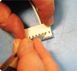
Remove probe terminal from connector.
-
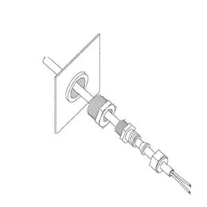
Locate where probe connects to the vat wall. Then, using a 1/2 in crowfoot wrench, remove compression fitting from 3/8 NPT to 1/8 NPT reducer.
-
Remove the probe through the fryer vat wall and discard.
-
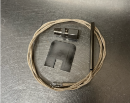
Open the temperature probe kit package. This includes the probe, compression fitting and parts, and insertion depth gauge.
-
Thoroughly clean the exposed inner threads of the reducer.
-
Apply high temperature thread sealant to threads of the compression fitting.
-
Install fitting into threads of reducer and tighten snug plus an additional half turn.
-
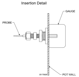
Place insertion depth gauge against vat (pot) wall as shown in the Insertion Detail image.
-
Push temperature probe through the vat wall until it contacts the gauge.
-
Tighten compression nut snug plus an additional half-turn to secure temperature probe in place.
-
Bunch excess probe wire length and use a wire tie as needed.
-
Reassemble or raise the appropriate outer panel using a cross tipped screwdriver.
-
Refill oil into the vat.
-
Press and hold Filter button until *FILTER MENU* displays.
-
Press P button until "5. FILL FROM PAN" displays.
-
Press 1 (FILL VAT).
-
Press 1 again and "FILLING" displays.
-
When oil reaches the fill line inside the vat, press 2 (STOP).
-
Continue pressing 2 until "EXIT" displays.
-
Inspect for leaks by checking the compression fitting before returning the fryer to service.
-
Restore power to fryer, turn power ON, and return fryer to service.

|
To avoid personal injury or property damage, before starting this procedure, move the main power switch to the off position. Disconnect the main circuit breakers at the circuit breaker box or unplug service cord from wall receptacle. |

|
Only perform this procedure when the unit is cool or severe burns may result. |
Note: Ensure the filter pan is empty before draining oil from the vat to the filter pan.
 Do not over tighten compression nut. This can damage the probe.
Related Content
Replacing the High Temperature Limit Control
Calibrating The Standard Single Stage Thermostat
Replacing the Temperature Probe
Replacing the Heating Elements
Replacing the Heating Contactors
Replacing the Main Power Switch
Troubleshooting the PFE 500 and 561 E-5 Oil Overheating Error Code
Troubleshooting PFE 561 E-6 Temperature Probe Error Code
Troubleshooting PFE 561 E-10 High Limit Error Code
Troubleshooting PFE 500 and 561 E-26 Heat Amps Locked On Error Code
Troubleshooting an E-92 Error Code
Troubleshooting PFE 561 E-92 24V Current Limiter (Fuse) Trip Error Code
Troubleshooting Oil Melting or Heating Slowly
Troubleshooting PFE 500 W-1 Low Voltage Warning
Troubleshooting PFE 500 W-2 Slow Heating Warning
Troubleshooting PFE 500 W-3 Was Not Ready Warning
Troubleshooting PFE 500 W-4 Slow Cooking Warning
Troubleshooting PFE 500 W-5 Slow Cooking Warning
Troubleshooting PFE 500 W-6 Slow Cooking Warning
Troubleshooting PFE 500 W-9 Discard Product Warning
Direct connect oil system operating instructions
Electronic C2000 Simple Control Retrofit Kit
4 Head PFE 500/ PFG 600 Removing the Lid
RLink programming instructions
Pressure Assist Kit Installation
PFE 500/PFG 600 Wi-Fi Verification and Troubleshooting Instructions
PFE 500/PFG 600 Hybrid Control Installation Instructions
2nd Generation Radio for SMS: Hardware Installation
2nd Generation Radio for SMS: Software Update
FM08-748 2nd Generation Radio for SMS: Troubleshooting
Instructions for Fryer Control Replacement Kits
SMS 20 Auto Polish Programming Instructions
CFA PFE 500 Hybrid Wi-Fi Status Check
Replacing the High Temperature Limit Control
Checking the Temperature Probe Calibration for Chick-fil-A
Replacing the Temperature Probe
Calibrating The Standard Single Stage Thermostat
Replacing the Gas Burner Assembly
Replacing the Main Power Switch
PFG 600 SSI Fryers Gas Valve Replacement Kit
Direct connect retrofit PFG 600
Direct connect retrofit PFG-600
PFG 600 Ignition Module Retrofit Kit
Troubleshooting E-1 Frypot Protection System (FPS)
Troubleshooting the PFG 600 E-12 FPS Probe Failure Error Code
Troubleshooting Oil Melting or Heating Slowly
Troubleshooting the PFG 600 E-20C No PV Error Code
Troubleshooting the PFG 600 E-20D Ignition Failure Error Code
Troubleshooting the PFG 600 E-92 24V Fuse Error Code
Installation of PFG 600 and PFG 600 SSI FM07-366 Electromechanical to C1000 Retrofit
PFG 600 SSI Electronic C1000 to C8000 Retrofit Kit
SAE Thread Filter Pump Installation
Pre VA SAE Thread Filter Pump Installation
Hybrid Control and Wi-Fi Installation
Replacing the High Limit Module
CFE 410/420 Troubleshooting the Solid State High Limit
CFE 410/420 Troubleshooting the E-5 Oil Overheating Error Code
CFE 410/420 Troubleshooting the E-6 Temperature Probe Error Code
CFE 410/420 Troubleshooting the E-10 High Limit Error Code
CFE 410/420 Troubleshooting the E-20A Fan Sensor Stuck On Error Code
CFE 410/420 Troubleshooting the E-26 Heat Amps Locked On Error Code
CFE 410/420 Troubleshooting the E-27 Amps Too Low Error Code
CFE 410/420 Troubleshooting an E-29 Error Code
CFE 410/420 Troubleshooting the Voltage Conversion
CFE 410/420 Troubleshooting the W-1 Low Voltage Error Code
CFE 410/420 Troubleshooting the W-2 Slow Heating Error Code
CFE 410/420 Troubleshooting the W-3 Was Not Ready Error Code
CFE 410/420 Troubleshooting the W-4 Slow Cooking Error Code
CFE 410/420 Troubleshooting the W-5 Slow Cooking Error Code
CFE 410/420 Troubleshooting the W-6 Slow Cooking Error Code
CFE 410/420 Troubleshooting the W-7 Low Amps Error Code
CFE 410/420 Troubleshooting the W-9 Discard Product Error Code
CFE 410/420 Troubleshooting the E-92 24V Current Limiter Fuse Tripped Error Code
Replacing the Momentary Switch
Replacing the Primary Contactor
Replacing the Heating Element Assembly
Replacing the Temperature Level Probe
Replacing High Limit Thermocouples
Troubleshooting the Solid State High Limit
Reference
PFE 500 and 561 Inspection and Planned Maintenance
PFE 500 KFC Annual Inspection Certification
PFG 600 Inspection and Planned Maintenance
PFG 600 KFC Annual Inspection Certification
CFE 410 and 420 Fryer Wiring Diagrams