Replacing the Relays
 Required tools
5/16" socket
 | To avoid electrical shock or property damage, disconnect power before installing or servicing equipment. A qualified technician must perform the service procedures. |
Disconnect the electrical supply to the cabinet.
Remove the two screws on the front of the control panel and pull control drawer out.
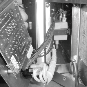
Before pulling the control panel out on the HC-944s, remove the four screws securing the control box.
The front relay controls the heat of the left drawer, the back relay controls the right drawer, and the middle relays control the middle drawers.
Checkout
| SHOCK HAZARD To avoid electrical shock, perform relay checks or transformer checks as described as instructions. |
The following checks are performed with the wall circuit breaker closed and the main power switch in the ON position. Extreme caution should be taken. Make connections before applying power, take reading, and remove power before removing meter leads, or electrical shock could result.
With no power (24 volts) going to the relay, 120 volts should show on the output side of the relay, and 0 volts on the input (24 volts).
With the component energized, 0 volts should show on the output side of the relay, and 12 volts on the input side.
If voltage varies from steps 3 and 4, remove power to unit pull input wires from relay and place leads of meter onto input wires. Reapply power to unit. When unit is running, if the input wires to relay shows 5vdc, the relay is faulty.
Replacing
Remove power supplied to unit.
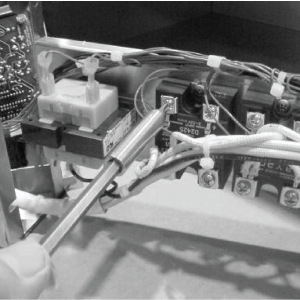
Label and remove wires from the appropriate relay.
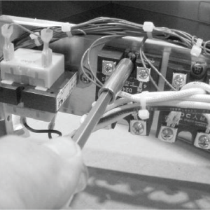
Using a crosshead screwdriver, remove the screws securing the relay and remove the relay from the unit.
NOTICE -
Failure to use the thermal joint compound will shorten the life of the relay.
Coat the back of the relay with the thermal joint compound and install new relay.
Replace control panel and unit is now ready for use.