Replacing the Selector Valve Drive Motor

|
To avoid electrical shock or property damage, move the power switch to OFF and disconnect power. |
-
Remove electrical power supplied to the unit.
-
Press on the switch from the inside of the fryer to release from the metal shroud.
-
Remove blower. See Replacing the Blower.
-
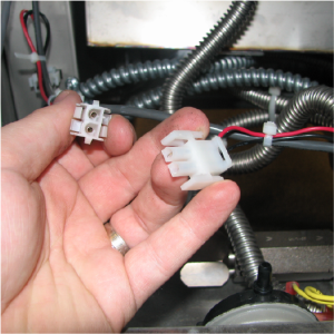
Disconnect the selector valve motor wires located in the back of the fryer.
-
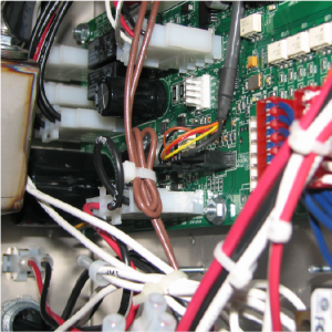
Move to the front of the fryer. Remove the AIF housing cover.
-
Locate and disconnect the encodes wires from the AIF board. Move to the back of the fryer.
-
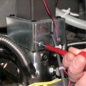
Remove the crosshead screw on the selector valve and remove the shield.
-
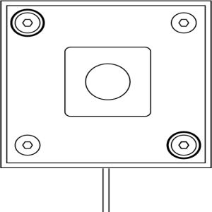
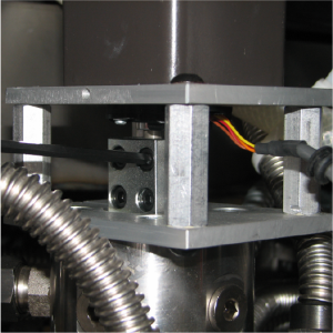
Using a 5/32 Allen wrench (recommended T-handle), remove the two diagonal screws circled.
-
Remove the shield.
-
Remove the remaining two screws.
-
Using a 5/32 Allen wrench (recommended T-handle), loosen the four screws on the coupler that is clamped onto the drive tube.
-
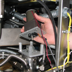
Lift motor off of selector valve body.
-
Move to the front of the fryer and locate port 10 (1) on the selector valve body (2). This will be the port located in the JIB area.
-
Using an adjustable wrench, remove the flex line from port 10.
-
Remove the fitting and set aside. This will allow the inside valve to be visible.
-
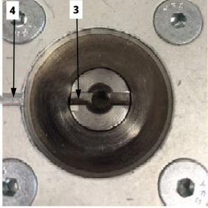
Manually turn selector valve body to home position by aligning the notch (3) with the alignment mark (4) as shown.
NOTICE -
To avoid product damage, ensure the AIF board is completely disconnected from power before plugging in motor encoder assembly.
-
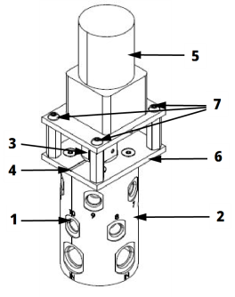
Place the new motor assembly (5) onto the selector valve mounting plate (6).
-
Attach motor encoder assembly to selector valve body by partially threading the four hex key screws (7) . Do not tighten.
NOTICE -
To avoid product damage, ensure the AIF board is completely disconnected from power when connecting harnesses.
Voltage spikes can damage the AIF board. No lights should be illuminated or flashing on the AIF board.
-
Connect encoder harness and 24VDC motor power supply harness from AIF board to motor encoder assembly.
-
Place AIF board box cover back into position.
-
Tighten the screws (7) with the 5/32 Allen wrench in a diagonal or crosshatch pattern.
NOTICE -
To avoid product damage:
-
Do not tighten the coupler at this time.
-
Do not install the shield at this time.
-
-
Reconnect the power cord to the unit. The selector valve will run a quick calibration to find the home position.
-
Once calibration is complete, tighten the coupler to the motors drive tube.
When tightening the coupler, the top two should have 50 inch pounds of toque and the bottom two should have 10 inch pounds torque.
-
With the coupler tightened to the correct specs, run a calibration to confirm all ports are properly aligned.
-
Install fitting back to selector valve and tighten. Then, tighten the flex line.
-
Install the shield and plate to the selector valve assembly.
Calibrating the Selector Valve
-
Press and release both filter buttons.
-
Press the left and right arrows until reaching “13.PUMPS & VALVES”.
-
Press the info button three times “SELECTOR VALVE AT HOME”.
-
Press product three then “✓” to confirm.
-
Once calibration has completed, check port 10 to confirm the inner hole is lined with valve body hole.
-
Continue with reassembly.
Related Content
Adjusting the Drain Valve Actuator
Troubleshooting Oil Not Pumping
Replacing the Flange Filter Pump and Motor Assembly
Replacing the Hubmounted Filter Pump and Motor Assembly
LVG 20X Troubleshooting the E-18 Level Probe Failure Error Code
Troubleshooting an E-82 Error Code
LVG 20X Troubleshooting the Oil Not Pumping
LVG 200 Generation 2 to Generation 4 Selector Valve Retrofit
Reference