crosshead screwdriver
5/32 hex wrench (recommended T-handle)
In-lb torque wrench
flat blade screw driver
Kit number
140776
Estimated Time
1 hour
Use these instructions to replace a Generation (Gen.) 2 style selector valve motor with a Gen. 4 style selector valve motor when servicing the LVG 200 model fryer.

|
Only perform this procedure when the fryer is cool or severe burns may result. |

|
Shock Hazard To avoid electrical shock or property damage, disconnect power before installing or servicing equipment. Lowering the control board exposes the technician to 240 VAC electricity inside the fryer. |
|
NOTICE - |
To avoid product damage, ensure the AIF board is completely disconnected from power before plugging in motor encoder assembly.
|
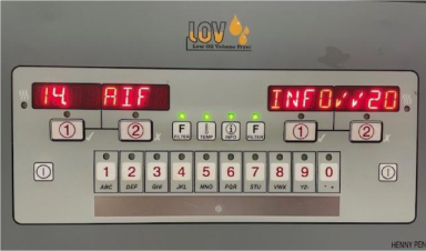
Checking Software Before Installation
NOTE: Before installing the selector valve retrofit, check AIF software version. The AIF software version must be revision level 20 or higher for Gen 4 selector valve to work properly.
-
Make sure control has power.
-
Press both F buttons to enter Info mode.
-
Press left F button until 14. AIF Info displays. The last digit(s) of the display will show the AIF software revision level.
Accessing the Selector Valve
-
Turn the power switch off.
-
Ensure fryer is cool to the touch before moving.
-
Pull out the fryer, and then unplug from the power source.
-
Using a crosshead screwdriver, loosen the four screws on the lower back shroud.
-
Remove shroud and set aside to access components.
-
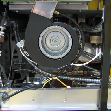
Gain access to blower in front of the selector valve.
-
Using a crosshead screwdriver, remove the three screws that secure the blower to the flue.
NOTE: One screw is located on the back side of the flue.
-
Cut zip ties that are holding the wires to the blower if needed and carefully set blower out of the way.
Disconnecting the Selector Valve and Motor
-
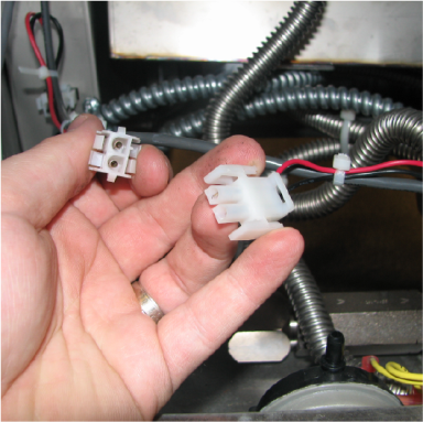
Disconnect the selector valve motor wires located in the back of the fryer.
-
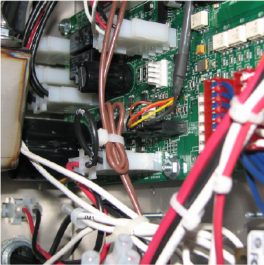
Move to the front of the fryer and remove the AIF board housing cover located on the right side of the fryer.
-
Locate and disconnect the encoder wires from the AIF board, remove encoder harness from fryer and discard.
-
Move to the rear of the fryer to access the selector valve.
Disassembling the Generation 2 Selector Valve and Motor
-
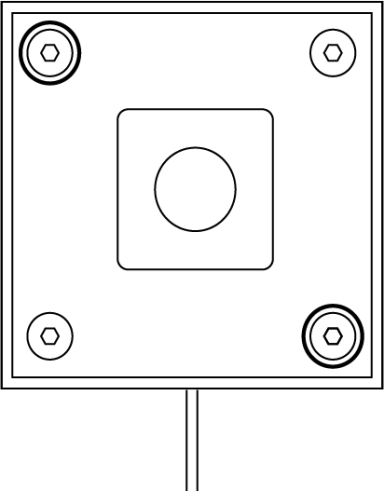
Remove the crosshead screw on the selector valve and remove the shield.
-
Using a 5/32 hex wrench (recommended T-handle), remove the two diagonal button cap screws circled in the image above and remove the shield.
-
Remove the remaining two screws.
-
Using a 5/32 hex wrench (recommended T-handle), loosen the four screws on the coupler that is clamped onto the drive tube.
-
Lift motor off of selector valve body.
-
Remove four flat head cap screws from the plate.
-
Remove valve plate from body.
Calibrating the Generation 4 Selector Valve Motor
|
NOTICE - |
To avoid product damage, ensure the I/O board is completely disconnected from power when connecting harnesses. Voltage spikes can damage the I/O board. No lights should be illuminated or flashing on the I/O board.
|
-
Connect the new Generation 4 motor to the existing power supply wiring harness and the new AIF wiring harness. Ensure only wiring is connected at this time.
Do not connect the motor to the selector valve body yet otherwise incorrect calibration may result.
-
Keeping hands away from the selector valve motor encoder shaft, connect power to the fryer. After several seconds the motor encoder assembly will start to turn and stop. This repeats a couple times. When the motor stops , calibration of the motor assembly is complete.
-
Disconnect power to the fryer.
Assembling the Generation 4 Selector Valve and Motor
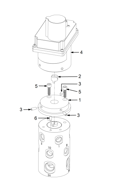
| Item No. | Description | Qty. |
|---|---|---|
| 1 | Adaptor Plate | 1 |
| 2 | Coupler | 1 |
| 3 | Threaded Pin | 3 |
| 4 | Motor | 1 |
| 5 | Fastenal | 2 |
| 6 | Fastenal | 1 |

-
Use a flat blade screw driver to turn the selector valve until Port 10 is open. NOTE: You can also align the open port indicator notch on the top of the spool and point towards the home port.
-
Place adapter plate on the top of valve body. Make sure the alignment pin engages the alignment hole.
-
Install 2 socket head cap screws. Torque to 10 in-lbs.
-
Place motor on top of adapter plate. Make sure the motor shaft engages the coupler.
-
Align through mounting holes on the motor with the thread mounting holes on the adapter.
-
Install 3 threaded pins. Torque to 30 in-lbs.
-
Secure the wiring harnesses.
Reassembling and Restarting the Fryer
-
Working in reverse, complete steps 8 through 1 of Accessing the Selector Valve and return the fryer to service.
-
Test operation of the selector valve by performing a filtration cycle.
Related Content
Adjusting the Drain Valve Actuator
Troubleshooting Oil Not Pumping
Replacing the Flange Filter Pump and Motor Assembly
Replacing the Hubmounted Filter Pump and Motor Assembly
Replacing the Selector Valve Drive Motor
LVG 20X Troubleshooting the E-18 Level Probe Failure Error Code
Troubleshooting an E-82 Error Code
LVG 20X Troubleshooting the Oil Not Pumping
Reference