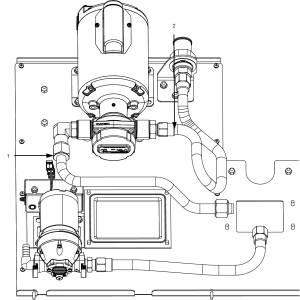
Replacing the Hubmounted Filter Pump and Motor Assembly
Included on units manufactured after September 2018.
Removing Debris from Pump

|
To avoid electrical shock or property damage, move the power switch to OFF and disconnect power. |
-
Loosen the four Allen head screws on the end of pump and remove the cover. (Removing the bottom rear panel may help in accessing the set screws.)

-
The inside is now exposed leaving a rotor and five Teflon rollers.
NOTICE -
Removing rotor will break filter pump body internal seal. To prevent product damage, DO NOT remove rotor from pump body.
-
Remove the rollers and clean.
-
Without removing the rotor, wipe it clean.
-
Place rollers back on rotor.
NOTE: A small amount of grease might be needed to hold the bottom roller into place until cover plate is put on. Make sure O-ring is in proper position on plate.
-
Align filter pump cover and secure with 4 screws.
Replacing the Hubmounted Filter Pump
-
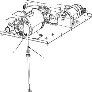
Remove the rear panel and the right side panel.
-
Using a 7/8 inch wrench, disconnect the outlet tube flexible line fitting (1) on the pump.
-
Using a 1 inch wrench, disconnect the suction tube pump fitting (2) .
-
Using a crosshead screw driver, remove access plate (3) from motor.
-
Disconnect the conduit wires (4) from the pump.
-
Using a 7/16 inch wrench, remove the 4 bolts (5) securing the motor to the mounting plate and remove the pump and motor assembly from fryer.
NOTE: Some units may only have 3 bolts securing the motor to the mounting plate.
-
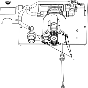
Align the new filter pump and motor assembly to the holes on the mounting plate and install with 4 bolts.
-
Reconnect the conduit wires to the pump.
-
Using a crosshead screw driver, install access plate on motor.
-
Attach the new straight SAE fitting to the motor.
-
Attach the new elbow SAE fitting to the motor.
-
Attach the straight fitting to the suction tube.
-
Attach the elbow fitting to the outlet tube.
Replacing the Motor Assembly
-
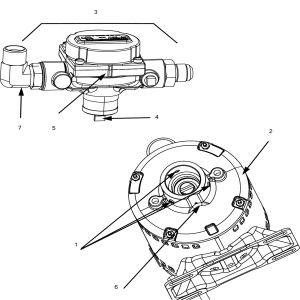
Remove the 3 screws (1) securing the pump to the motor and pull the pump (2) from the motor (3).
-
Align the shaft of the motor (4) with the pump ensuring that the groove on the motor (5) aligns with the groove on the pump (6).
NOTE: This should be the 3 o’clock position. The inlet port with the attached elbow SAE fitting (7) should be on the side closest to the JIB pump.
-
Press pump onto shaft of motor.
-
Secure the pump onto the motor with the 3 screws.
Related Content
Replacing the Flange Mount Filter Pump and Motor
Replacing the Filter Motor Relay
Replacing the Filter Pan Switch
Replacing the Oil Level Probes
Replacing the Drain Rod Microswitch
Replacing the Express Filter PC Board
Adjusting the Drain Valve Actuator
Troubleshooting the Check Pan Message on Evolution Elite Fryers
Troubleshooting EEE 14X Oil Not Pumping Error Code
Troubleshooting EEE 14X E-15 Drain Open Error Code
Reference