Troubleshooting the E-15 Drain Not Opening and Closing Error Code
Overview
The E-15 C and P error codes indicates that the control system is not receiving feedback confirming that the drain valve has fully closed or opened completely. This issue can arise due to various reasons, including debris obstructing the valve. This article provides a step-by-step guide to help service technicians diagnose and resolve the E-15C error code efficiently.
E-15 Errors
-
E-15P: Drain not opening (Drain open signal not found)
-
E-15C: Drain not closing (Drain closed signal not found)
Call Avoidance Steps
To help the end user resolve the issue without a service call:
-
Inspect the Drain Valve: Check for any visible debris or obstructions in the drain valve.
-
Clear Debris: Use Filter menu step 4. Drain to Pan to open the drain valve. Use a straight brush to push through any debris that might be clogging the drain valve.
-
Ensure Proper Opening (E-15P): Verify that the drain valve is opening completely after clearing any obstructions.
-
Ensure Proper Closure (E-15C): Verify that the drain valve is closing completely after clearing any obstructions.
Field Troubleshooting
If the E-15 C or P error persists after performing the call avoidance steps, follow these troubleshooting steps.
Recommended Parts:
PQE 500 Pressure Fryer Series
-
Drain Valve
-
Control Board
Recommended Tools
-
Straight Brush: For clearing debris from the drain valve.
-
Basic hand tools (screwdrivers, pliers, etc.)
-
Multimeter
Troubleshooting Obstructions or Valve Failures
-
Check for Obstructions:
-
Remove any remaining debris in the drain valve.
-
Ensure the valve moves freely without any resistance.
-
Inspect the Drain Valve Mechanism:
-
Verify that the drain valve mechanism is not damaged or worn out.
-
Replace the drain valve if necessary.
-
Verify Feedback Signals:
-
Ensure that the feedback signals from the drain valve to the control system are being transmitted correctly.
-
Follow the tech mode input/output topic to test the 24VDC signals.
-
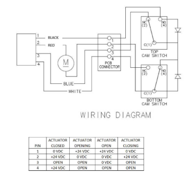
Use the T-19 mode, and the diagram below to test the 24VDC signals.
-
Check the P9 RDV1-RDV4 wiring and connections on the back of the control and to the drain valve for any damage or loose components.
-
Replace the drain valve if necessary:
-
RDV1 - Pin 3 (Black)
-
RDV2 - Pin 4 (Red)
-
RDV3 - Pin 1 (Blue)
-
RDV4 - Pin 2 (White)
-
Test the Control Board:
-
Check the control board for any signs of damage or malfunction.
-
Replace the control board if necessary.