OGA-OFG 32X Replacing the Vacuum Switch
Drill with crosstip bit
Needle nose pliers
Measuring tape
Kit number
14894
Estimated Time
30 minutes
Follow these instructions to safely replace the vacuum switch in the fryer.

|
Only perform this procedure when the unit is cool or severe burns may result. |
|
|
To avoid electrical shock or property damage, disconnect power before installing or servicing equipment. A qualified technician must perform the service procedures. |
IMPORTANT! For proper function, the vacuum switch MUST BE MOUNTED in the orientation shown in these instructions. Installation location of the new vacuum switch varies by version.
Preparing Fryer
-
Turn power switch off.
-
Ensure fryer is cool to the touch before moving.
-
Pull out the fryer and unplug from power source.
-
Using the drill with crosshead bit, remove control mounting screw(s) and carefully lower control down.
Removing Vacuum Switch
-
Disconnect tubing and two wires from the existing vacuum switch.
-
Remove existing vacuum switch.
Replacing Vacuum Switch - Version 1 Tan
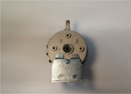
NOTE: This step applies to Version 1 only. If you have a Version 2 switch, please proceed to Replacing Vacuum Switch - Version 2 steps below.
-
Position vacuum switch 1/8 inches from I/O board to corner of the bracket and 3/8 inches from top of the shroud to bracket. Mount with the two self-drilling screws supplied in the kit.
-
Reconnect the tubing and wires.
-
Work in reverse, complete steps 4 through 1 in Preparing Fryer and return fryer to service.
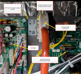
NOTE: The picture shows an auto-lift unit. For a non-auto-lift unit, the auto-lift board is not present, but the switch should be mounted in the same location.
NOTE: Wires may be attached to either terminal.
Replacing Vacuum Switch - Version 2 Gray
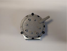
NOTE: This step applies to Version 2 only. If you have a Version 1 switch, please proceed to Replacing Vacuum Switch - Version 1 steps above.
-
Position vacuum switch 1-7/8 inches from I/O board to corner of the bracket and 1/2 inches from top of shroud to bracket. Mount with the two self-drilling screws supplied in the kit.
-
Reconnect the tubing and wires.
-
Work in reverse, complete steps 4 through 1 in Preparing Fryer and return fryer to service.
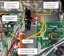
NOTE: The picture shows an auto-lift unit. For a non-auto-lift unit, the auto-lift board is not present, but the switch should be mounted in the same location.
NOTE: Wires may be attached to either terminal.
Related Content
Replacing the Complete Control Panel
Replacing the I/O Power Supply Board Assembly
Replacing the Speak Assembly (Gas Units)
Replacing the Speaker Assembly (Electric Units)
OFE 32X C1000 to C8000 Retrofit Kit
OFG 32X C1000 to C8000 Retrofit Kit
Troubleshooting an Unresponsive Control Displaying 8's
Troubleshooting the OFE and OFG 32X Fryer E-41 System Data Lost Error Code
32X Direct Connect Oil System Operating Instructions
Direct Connect Retrofit Instructions
OFE 32X Open Drain Switch Retrofit Kit
OFG 322/323 Open drain switch retrofit kit instructions
OFE 32X Open Drain Switch Retrofit Kit
OFG 32X Open Drain Switch Retrofit
OGA-OFG 32X Ignition Module Retrofit
OFG/OGA 32X Replacing Gas Valve Kit
OFE 32X Installing the Spreader Bar
OFE 32X Reinforcing the Basket Rest
OFX 32X Replacing the Motor Shield
OFE 32X Installing the Filter Pump
OFE 32X Chick-Fil-A Element Bracket
OFE 32X Conversion from Full Pan to Single Pan
Reflashing the CFA ARM-Based Control
Reference