Installing the SiteSage Radio Hardware
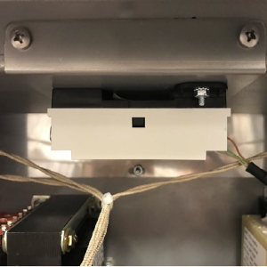
This component is located behind the left control panel.


|
To avoid electrical shock or property damage, move the power switch to OFF and disconnect power. |
-
Remove two screws from control panel on first left well and tilt down.
-
Center the control panel radio assembly against component shroud in first left well.
-
Mark location for holes.
-
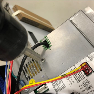
Drill .140 diameter holes in the locations you marked.
-
Mount radio assembly onto component shroud with two screws.
-
Remove existing control panel access covers and discard.
-
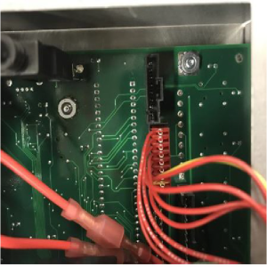
Insert radio harness connector into each control.
-
Install new control access covers onto controls using existing hardware.
-
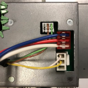
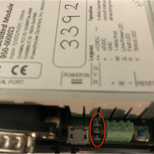
Insert SiteSage radio wires in terminals.
-
Insert control communication wires into control and run harnesses to all controls except last.
-
On last control, insert control communication wire into control and attach resistor to other end of harness.
-
Run harness with resistor to control.
-
Lift all but first left control panel and secure with two screws per panel.
-
Move the power switch to ON.
-
Ensure the LED light illuminates and the radio functions properly.
-
Lift first left control panel and secure with two screws.
-
Follow procedure in Enabling the Control MODBUS.
Enabling the Control MODBUS
-
Press and hold the P button until LEVEL 2 displays on the control.
-
Use the left/right arrow button to navigate to the DATA COMM menu.
-
Using the number pad, enter password 123.
-
Use left arrow button to navigate to DC-11 MODBUS ENABLED.
-
Use the up/down button to select YES.
-
Press and hold the P button to save selection and exit DATA COMM menu. Control and radio are able to communicate after MODBUS is enabled.
-
Connect the radio to the store network/gateway. The network/gateway can request information from the radio which acquires the requested information from the control and then returns the information to the network/gateway.
Related Content
Replacing the Control Panel and Menu Card
Replacing the Main Power Switch
Resetting, Checking and Replacing the Breaker
Replacing the Express Filter PC Board
Smart Touch Software Installation Instructions
Troubleshooting EEE 14X E-41 Programming Settings Lost Error Code
Troubleshooting EEE 14X E-60 AIF Communication Error Code
Reference