Smart Touch Software Installation Instructions
Kit number
140402
Estimated Time
5 minutes per Control
The following instructions are for installing software on new units or when controls are replaced.
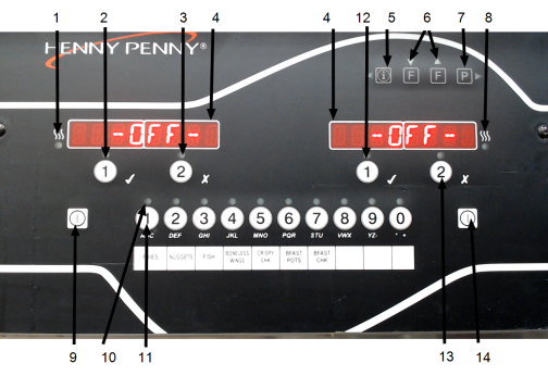
Control Features
| Item | Description | Function |
|---|---|---|
| 1 | Left Heat LED | This LED lights when the control calls for heat for the left vat, and the burners ignite and heat the oil. |
| 2 | Left Timer 1 Button | During normal operation, press this button to start and stop cook cycles for the left basket or press to change displayed product. Also used for "ü" to indicate yes or to confirm. |
| 3 | Left Timer 2 Button | During normal operation, press this button to start and stop cook cycles for the left basket or press to change displayed product. Also used for "X" to indicate no or to cancel. |
| 4 | Digital Display | Displays the product codes, the timer countdown during cook cycles, the selections in the program mode, the temperature of the oil by pressing the Info button and the error codes. Also, displays in several languages. |
|
5 |
Info Button |
Press once to view actual oil temperature. Press twice to view oil set-point temperature. Press three times to view recovery information for each vat from 250°F to 300°F (121°C to 149°C). Used in programming modes and as a button to back up to a previous parameter in program and filter modes. |
| 6 | Filter Button | Used to access the filter menu and for the up and down arrow buttons. Press once to view the number of cook cycles before next filter in Global Filter or the mode percentage of filter allowance in Mixed Filter. Press twice to view the time and date of the most recent filter on each vat. Press three times to view the number of hours of use of the filter pad presently in the drain pan. |
| 7 | Program Button | Used to access the program modes and the right arrow button to advance to the next parameters in program and filter modes. Press to select 2nd language and volumes. |
| 8 | Right Heat LED | This LED lights when the control calls for heat for the right vat and the burners ignite and heat the oil. |
| 9 | Left Heat Button | Press to turn on and off the heat system for the left vat(s) and on full vats either heat button can be used. |
|
10 |
Product LED |
Each product button LED lights when that product has been selected or when it is compatible with cook temperature. |
| 11 | Product Button | Press to select the desired product. Press to place the letters under the button during naming a product in program mode. |
| 12 | Right Timer 1 Button | During normal operation, press this button to start and stop cook cycles for the right basket. Press to change displayed product and used for "ü" to indicate yes or to confirm. |
| 13 | Right Timer 2 Button | During normal operation, press this button to start and stop cook cycles for the right basket. Press to change displayed product and used for "X" to indicate no or cancel. |
| 14 | Right Heat Button | Press to turn on and off the heat system for the right vat(s). On full vats either heat button can be used. |
Installing Software - New Units and Replacement Controls
-
Do one of the following:
-
For new units, locate the USB drive provided with the unit, and then continue to Step 2.
-
For replacement controls, follow steps from Exporting from Existing Control first, and then proceed with Step 2.
-
-
Press the left Heat button (9) or the right Heat button (14). This will turn on the heat system.
-
Press 1, 2, 3 Product buttons to enter Setup mode. The message FLASH SOFTWARE and INSERT USB will display.
-
Insert the USB drive into the USB port, located below the control. The LOAD SW and CUSTOMER NAME will display. After the customer's name displays, the following will display:
-
MAN DRAN - Manual pull handle software
-
AUTO DRAN - Smart Touch filtration software
-
-
Press the 1 button to select the software. FLASH and the software part number will display.
-
Press the 1 button to load the new software. CONFIRM will display.
-
Press the 1 button to confirm. CHECKING FILE displays with dash marks, and then UPDATING SOFTWARE displays for 3 to 5 seconds. When INIT DONE displays, the control beeps and returns to Setup mode.
-
Complete all remaining steps in Setup mods to finish the reflashing process.
Exporting from Existing Control
For replacement controls, locate the USB drive provided with the new control assembly. If you are updating an existing control to the same version of the same version of software as the rest on the fryer, then you will need to provide a blank USB drive (preferably 8GB or smaller).
-
Insert the USB drive into the USB port, located below the control.
-
Press either the left Heat button (9) or right Heat button (14).
-
Press and hold PROG button until LEVEL 2 displays.
-
Press the ◄ or ► until FLASH SW displays.
-
Enter password 11221122.
-
Press the Right Time 2 button (13) so that MAIN FLASH displays.
-
Use ▲ and ▼ to select EXPORT.
-
Press the 1 button to export file to the USB drive. WRITING, a software part number, and revision will display. The control returns to the MAIN FLASH menu when complete.
-
Remove the USB drive, and then do one of the following:
-
For new units and new controls, continue with the steps in the Installing software - New Units and Replacement Controls section.
-
For existing controls, continue with the steps in the Initialize Existing Control to Factory Settings and Default Set-points section.
Programming Existing Control
- Provide a USB drive (preferably 8GB or smaller) which already contains Evolution Elite software from another control. See Exporting from Existing Control.
- Insert the USB drive into the USB port, located below the control.
- Press either the left Heat button (9) or right Heat button (14).
- Press and hold PROG button until LEVEL 2 displays.
- Press the ◄ or ► buttons and scroll until FLASH SW displays.
- Enter password 11221122.
- Use ▲ and ▼ buttons to select the desired version of software.
- Press 1 button to start the programming process.
- Press 1 button to confirm the programming process. CHECKING FILE will display followed by dashes and UPDATING SOFTWARE.
- Continue to the Initialize Existing Control to Factory Settings and Default Set-points section. These steps must be completed before the change takes place.
Initializing Existing Control to Factory Settings and Default Set-points
NOTE: To keep the current set-points, DO NOT initialize the controls.
-
Press and hold Program button for 5 seconds until LEVEL 2, and then SP PROG ad ENTER CODE will displays.
-
Press the Program button 4 times. TECH and ENTER CODE flashes in the left display.
-
Enter code 11221122 (using first 2 product buttons). T-1 SOFTWARE flashes in the left display and EV-ELITE displays on the right.
-
Press the ◄ or ► buttons and scroll to T-25 Total Initialization.
-
Press and hold the 1 button to initialize the control. The control counts down and when it reaches zero the initialization begins. The initialization completes and the control returns to the menu.
-
Press the Program button to exit Tech Mode.
Potential Errors
In the event of an error message listed below, follow the corrective action step to correct.
| Error | Definition | Correction |
|---|---|---|
| TOO MANY FILES | The control recognizes too many .hpf files on the USB drive. | Plug into a computer and remove unwanted .hpf files. |
| FILE NOT FOUND | The control cannot locate a .hpf file on the USB drive. | Upload a .hpf file onto the USB drive. |
| FILE NOT FORMATED |
USB drive is not properly formatted. | A new .hpf file needs uploaded to the USB drive. |
| INSERT USB DRV | No USB is detected in the USB port during one of the procedures listed above. | Insert USB. |
Related Content
Replacing the Control Panel and Menu Card
Replacing the Main Power Switch
Resetting, Checking and Replacing the Breaker
Installing the SiteSage Radio Hardware
Replacing the Express Filter PC Board
Troubleshooting EEE 14X E-41 Programming Settings Lost Error Code
Troubleshooting EEE 14X E-60 AIF Communication Error Code
Replacing the Control Panel and Menu Card
Replacing the Main Power Switch
Troubleshooting EEG 14X E-41 Programming Settings Lost Error Code
Troubleshooting EEG 14X E-60 AIF Communication Failure Error Code
Replacing the EEG Fryer Generation 4 Selector Valve Motor
Replacing the Express Filter PC Board
Replacing the Main Power Switch
Replacing the Control Panel and Menu Card
Resetting, Checking and Replacing the Breaker
Replacing the EEE 153 and 154 Time Delay Relays
Troubleshooting an EEE 15X E-60 AIF Communication Failure
Wendy’s Autonomous Power Switching Circuit Field By-Pass
Troubleshooting EEE 15X E-41 Programming Settings Lost Error Code
Replacing the Main Power Switch
Replacing the Control Panel and Menu Card
Replacing the Express Filter PC Board
Troubleshooting EEG 15X E-41 Programming Settings Lost Error Code
Troubleshooting EEG 15X E-60 AIF Communication Failure Error Code
Replacing the Control Panel and Menu Card
Resetting, Checking and Replacing the Breaker
Replacing the Main Power Switch
Replacing the Express Filter PC Board
Replacing the Control Panel and Menu Card
Replacing the Main Power Switch
Troubleshooting EEG 24X Zigbee Radio Connection
Troubleshooting EEG 16X and 24X E-4 Control Overheating Error Code
Troubleshooting EEG 16X and 24X E-41 Programming Settings Lost Error Code
Troubleshooting EEG 16X and 24X E-60 AIF Communication Failure Error Code
Replacing the Bulk Fill Selector Valve
Replacing the Control Panel and Menu Card
Replacing the Main Power Switch
Troubleshooting EEG 25X E-41 Programming Settings Lost Error Code
Troubleshooting EEG 25X E-60 AIF Communication Failure Error Code
Reference
EEG 16X and 24X Plumbing Diagram