Wendy’s Autonomous Power Switching Circuit Field By-Pass
wire cutters
needle nose pliers
nut driver
wire zip ties
wire nuts
Part 1
Part 2
Part 3
Kit number
140443
Estimated Time
15-20 minutes
Overview
Wendy's is removing the requirement for the autonomous power switching relay, timer, and timer base from all Wendy's Electric Evolution Elite Fryers. The autonomous control power switching feature is to be discontinued on production units as well as units in the field. All units built after serial number BL1507010 will not have the autonomous control power switching feature.
Bypass and removal of relays, timer, and timer base should be done proactively on units that have been experiencing failures on the autonomous power switching relay. The error code E‐60 is generated when failure occurs. Check error codes in HP info mode 1. E‐LOG.
While on site, units should be thoroughly evaluated to determine what was causing power switching system to be activated; losing power to vat 1.
Fryers that have not experienced issues with autonomous power switching relay should have the relay bypassed the next time a service call is initiated on the unit. It is not expected that service calls be scheduled only for bypass and removal of the relay. If the fryer is under labor warranty, Henny Penny will cover an additional 30 minutes to remove the relay from the circuit. It must be clearly called out in the claim comments that this work was performed in addition to the work that was also performed for the service call.
Procedure
-
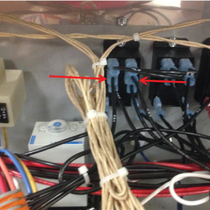
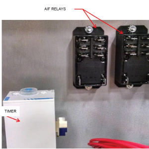
Remove RS3 and RS4 from AIF relay.
-
Do one of the following:
-
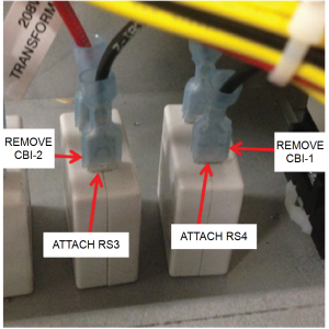
For 208/240 units - Remove CB1-1 and CB1-2 from the two pump circuit breakers.
-
For 380-415 units – Remove only CB1-2 from the pump circuit breaker.
-
-
Do one of the following:
-
For 208/240 units - Attach RS3 and RS4 to the pump circuit breaker terminals.
-
For 380-415 units – Attach only RS4 to the pump circuit breaker terminal.
-
-
For 380-415 units - Remove L2A-2 from timer and RS3 from splice/lever nut, then attach L2A-2 to splice/lever nut in place of RS3. Discard RS3.
-
Do one of the following:
-
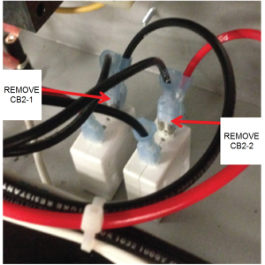
For 208/240 units - Remove CB2-1, CB2-2 and the two blade adapter (piggyback) terminals from the Control BD and Solenoid Circuit Breakers.
-
For 380-415 units - Remove only CB2-1, and the blade adapter (piggyback) terminal from the Control BD and Solenoid Circuit Breaker.
-
-
Do one of the following:
-
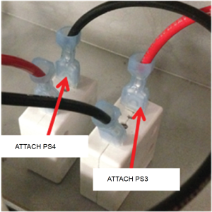
For 208/240 units - Re-attach PS3 and PS4 to Control BD and Solenoid Circuit Breaker terminals.
-
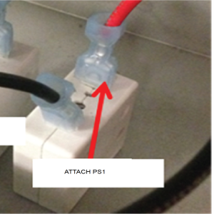
For 380-415 units - Re-attach PS1 to Control BD and Solenoid Circuit Breaker terminal.
-
-
Remove the two AIF relays and the timer along with any unused wire harnesses still attached to those components. Verify that no additional loose wires are left over.
-
Apply wire ties to the secure the loose wires.
-
Verify the following operation:
-
Each control can be powered on and off individually.
-
With power to Vat #1 turned off, verify that the remaining vats can be filtered.
-
Related Content
Replacing the Express Filter PC Board
Replacing the Main Power Switch
Replacing the Control Panel and Menu Card
Resetting, Checking and Replacing the Breaker
Replacing the EEE 153 and 154 Time Delay Relays
Smart Touch Software Installation Instructions
Troubleshooting an EEE 15X E-60 AIF Communication Failure
Troubleshooting EEE 15X E-41 Programming Settings Lost Error Code
Reference