Replacing the High Limit
This is a safety, manual reset control, which senses the temperature of the oil. If the oil temperature exceeds 425°F (218°C), this switch opens and shuts off the heat to the vat. When the temperature of the oil drops to a safe operation limit, manually reset the control by pressing the reset button.
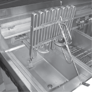
The reset button is located in the hinge of the element. Use a small screwdriver or Allen wrench, gently push it into the hole in the heating element hinge; if high limit does not reset, high limit must be replaced. If high limit resets, the oil starts heating.
Checkout

|
To avoid electrical shock or property damage, move the power switch to OFF and disconnect power. |
The oil temperature must be below 380° F (193° C) to accurately perform this check.
-
Remove control panel and hinge it down.
-
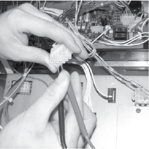
Referring to the decal on the rear of the control panel, locate P9 connector (left vat-split vat) or P10 connector (full or right vat).
-
Attempt to reset the high limit and then pull the connector from the board and check for continuity between the 2 appropriate pins. If the circuit is open then continue replacement procedure. (If the circuit is closed, the high limit is not defective).
Replacing
If the tube is broken or cracked, the control opens, shutting off electrical power. The control cannot be reset.
-
Using a crosshead screwdriver, or screw gun, remove nine screws and rear panel.
-
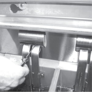
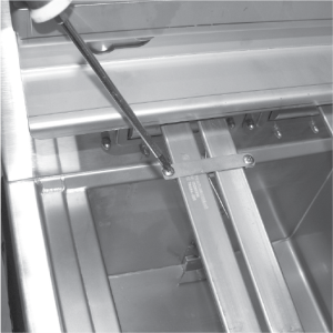
Using 3/8 inch wrench or socket, remove two acorn nuts securing bracket to unit.
-
Using a crosshead screwdriver, remove three screws securing the high limit to the bracket.
-
Use the lift tool and lift the hinged element from the vat.
-
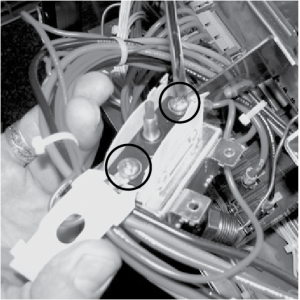
Pull the high limit from the bracket, pull back the cardboard protector, and remove the two electrical wires from the high limit control.
-
Drain oil from vat, by pressing and holding a Filter button until *FILTER* *MENU* displays. Then, once “1.AUTO FILTER” displays, press the Down arrow button three times until “4. DRAIN TO PAN” displays. Press √ button and “DRAIN TO PAN” “YES NO” displays. Press √ button again display shows “DRAINING”, and oil drains from vat. Once oil has drained, display shows “VAT EMTY” “YES NO”. Visually check that vat is empty and press √ button, display shows “DRAIN CLOSING...” and drain closes.
-
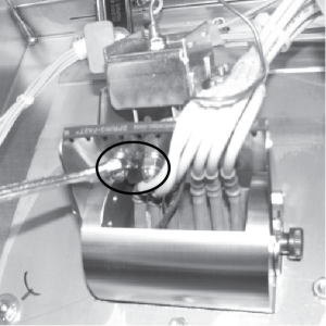
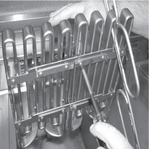
While holding top-side capillary bracket, use a crosshead screwdriver and remove the screws securing capillary bulb to the lower element bracket. Remove both front and rear capillary brackets.
-
Using a crosshead screwdriver, remove the screws securing the capillary bulb to the upper element brackets.
-
Remove high limit bulb from element and carefully straighten the capillary tube and pull the high limit control from the rear of the unit.
NOTE: It’s important not to damage the capillary bulb when removing or installing the high limit from the unit. Undamaged high limits returned for warranty can be evaluated for cause of failure.
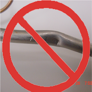
Capillary bulbs or tubes damaged during installation causes high limit to fail prematurely.
-
Insert new high limit capillary through hole in rear of fryer and slide high limit into bracket. Make sure the plunger on high limit makes good contact with the reset plate and then secure with the three screws.
-
Slide bracket and high limit assembly into place and secure with the two acorn nuts removed in step 3.
-
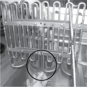
Remove basket hanger, lift heating element, and insert allen wrench, screwdriver or extra reset pin into hole in heater element pivot from the front of the fryer.
-
Push the tool in all the way visually making sure plunger engages and pushes red plastic reset button entirely into switch. Hold the tool in the depressed position.
-
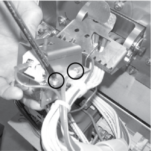
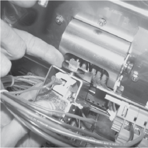
While holding tool in fully depressed position, inspect high limit switch reset button position within the bracket.
-
If any red plastic of reset button can be seen, adjust bracket in or out using needle nose pliers so the angle of the assembly matches the angle of the plunger.
-
If only brass is visible as shown at left, the adjustment is acceptable.
-
-
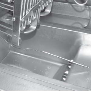
Carefully slide capillary bulb up through the element, from the rear of the elements.
-
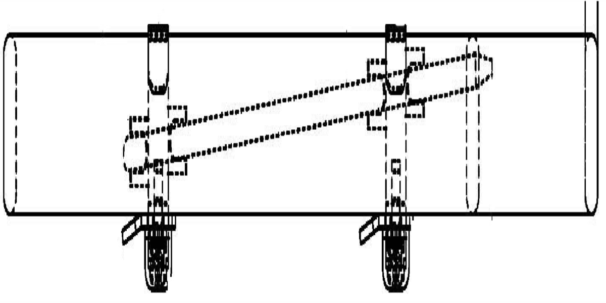
Using the capillary brackets removed in step 3 (see below) attach capillary to the lower brackets, aligning the capillary so it does NOT touch the element. (See side-view drawing below for proper installation.)
-
Secure the capillary to the upper brackets.
-
Replace basket hanger, rear cover and reconnect power.
-
Lower element back into vat and fill vat by pressing and holding a filter button until *FILTER* *MENU* displays. Then once “1.AUTO FILTER” displays, press the Down arrow button four times until “5.FILL POT FROM DRN PAN” displays. Press √ button and “FILL POT FROM DRN PAN” “YES NO” displays. Press √ button again, display shows “FILLING” “STOP?”and oil fills vat. Press √ button again, display shows “FILL POT FROM DRN PAN” “YES NO”. When vat is full, press X twice to return to normal operation.
For additional troubleshooting refer to the JWF Light Code Chart.
Thermoelectric voltage as a function of temperature (°F); reference junctions at 32 °F.
| F | 0 | 1 | 2 | 3 | 4 | 5 | 6 | 7 | 8 | 9 | 10 |
|---|---|---|---|---|---|---|---|---|---|---|---|
| 50 | 0.507 | 0.535 | 0.563 | 0.592 | 0.620 | 0.649 | 0.677 | 0.705 | 0.734 | 0.762 | 0.791 |
| 60 | 0.791 | 0.819 | 0.848 | 0.876 | 0.905 | 0.933 | 0.962 | 0.991 | 1.019 | 1.048 | 1.076 |
| 70 | 1.076 | 1.105 | 1.134 | 1.162 | 1.191 | 1.220 | 1.249 | 1.277 | 1.306 | 1.335 | 1.364 |
| 80 | 1.364 | 1.364 | 1.392 | 1.421 | 1.450 | 1.479 | 1.508 | 1.566 | 1.594 | 1.623 | 1.652 |
| 90 | 1.652 | 1.681 | 1.710 | 1.739 | 1.768 | 1.797 | 1.826 | 1.855 | 1.884 | 1.913 | 1.942 |
| 100 | 1.942 | 1.972 | 2.001 | 2.030 | 2.059 | 2.088 | 2.117 | 2.146 | 2.175 | 2.205 | 2.234 |
| 110 | 2.234 | 2.263 | 2.292 | 2.322 | 2.351 | 2.380 | 2.409 | 2.439 | 2.468 | 2.497 | 2.527 |
| 120 | 2.527 | 2.556 | 2.585 | 2.615 |
2.644 |
2.673 | 2.703 | 2.732 | 2.762 | 2.791 | 2.821 |
| 130 | 2.821 | 2.850 | 2.880 | 2.909 | 2.938 | 2.968 | 2.997 | 3.027 | 3.057 | 3.086 | 3.116 |
| 140 | 3.116 | 3.145 | 3.175 | 3.204 | 3.234 | 3.264 | 3.293 | 3.323 | 3.353 | 3.382 | 3.412 |
| 150 | 3.412 | 3.442 | 3.471 | 3.501 | 3.531 | 3.560 | 3.590 | 3.620 | 3.650 | 3.679 | 3.709 |
| 160 | 3.709 | 3.739 | 3.769 | 3.798 | 3.828 | 3.858 | 3.888 | 3.918 | 3.948 | 3.977 | 4.007 |
| 170 | 4.007 | 4.037 | 4.067 | 4.097 | 4.127 | 4.157 | 4.187 | 4.217 | 4.246 | 4.276 | 4.306 |
| 180 | 4.306 | 4.336 | 4.366 | 4.396 | 4.426 | 4.456 | 4.486 | 4.516 | 4.546 | 4.576 | 4.606 |
| 190 | 4.606 | 4.636 | 4.666 | 4.696 | 4.726 | 4.757 | 4.787 | 4.817 | 4.847 | 4.877 | 4.907 |
| 200 | 4.907 | 4.937 | 4.967 | 4.997 | 5.028 | 5.058 | 5.088 | 5.118 | 5.148 | 5.178 | 5.209 |
| 210 | 5.209 | 5.239 | 5.269 | 5.299 | 5.329 | 5.360 | 5.390 | 5.420 | 5.450 | 5.480 | 5.511 |
| 220 | 5.511 | 5.571 | 5.571 | 5.602 | 5.632 | 5.662 | 5.692 | 5.723 | 5.753 | 5.783 | 5.814 |
| 230 | 5.814 | 5.874 | 5.874 | 5.905 | 5.935 | 5.965 | 5.996 | 6.026 | 6.056 | 6.087 | 6.117 |
| 240 | 6.117 | 6.178 | 6.178 | 6.208 | 6.239 | 6.269 | 6.299 | 6.330 | 6.360 | 6.391 | 6.421 |
| 250 | 6.421 | 6.452 | 6.482 | 6.512 | 6.543 | 6.573 | 6.604 | 6.634 | 6.665 | 6.695 | 6.726 |
| 260 | 6.726 | 6.756 | 6.787 | 6.817 | 6.848 | 6.878 | 6.909 | 6.939 | 6.970 | 7.000 | 7.031 |
| 270 | 7.031 | 7.061 | 7.092 | 7.122 | 7.153 | 7.184 | 7.214 | 7.245 | 7.275 | 7.306 | 7.336 |
| 280 | 7.336 | 7.367 | 7.398 | 7.428 | 7.459 | 7.489 | 7.520 | 7.550 | 7.581 | 7.612 | 7.642 |
| 290 | 7.642 | 7.673 | 7.704 | 7.734 | 7.765 | 7.795 | 7.826 | 7.857 | 7.887 | 7.918 | 7.949 |
| 300 | 7.949 | 7.979 | 8.010 | 8.041 | 8.071 | 8.102 | 8.133 | 8.163 | 8.194 | 8.225 | 8.255 |
| 310 | 8.255 | 8.286 | 8.317 | 8.347 | 8.378 | 8.409 | 8.439 | 8.470 | 8.501 | 8.532 | 8.562 |
| 320 | 8.562 | 8.593 | 8.624 | 8.654 | 8.685 | 8.716 | 8.747 | 8.777 | 8.808 | 8.839 | 8.869 |
| 330 | 8.869 | 8.900 | 8.931 | 8.962 | 8.992 | 9.023 | 9.054 | 9.085 | 9.115 | 9.146 | 9.177 |
| 340 | 9.177 | 9.208 | 9.238 | 9.269 | 9.300 | 9.331 | 9.362 | 9.392 | 9.423 | 9.454 | 9.485 |
| 350 | 9.485 | 9.515 | 9.546 | 9.577 | 9.608 | 9.639 | 9.669 | 9.700 | 9.731 | 9.762 | 9.793 |
| 360 | 9.793 | 9.823 | 9.854 | 9.885 | 9.916 | 9.947 | 9.977 | 10.008 | 10.039 | 10.070 | 10.101 |
| 370 | 10.101 | 10.131 | 10.162 | 10.193 | 10.224 | 10.255 | 10.285 | 10.316 | 10.647 | 10.378 | 10.409 |
| 380 | 10.409 | 10.440 | 10.470 | 10.501 | 10.532 | 10.563 | 10.594 | 10.625 | 10.655 | 10.686 | 10.717 |
| 390 | 10.717 | 10.748 | 10.779 | 10.810 | 10.840 | 10.871 | 10.902 | 10.933 | 10.964 | 10.995 | 11.025 |
| 400 | 11.025 | 11.056 | 11.087 | 11.118 | 11.149 | 11.180 | 11.211 | 11.241 | 11.272 | 11.303 | 11.334 |
| 410 | 11.334 | 11.365 | 11.396 | 11.426 | 11.457 | 11.488 | 11.519 | 11.550 | 11.581 | 11.612 | 11.642 |
| 420 | 11.642 | 11.673 | 11.704 | 11.735 | 11.766 | 11.797 | 11.828 | 11.858 | 11.889 | 11.920 | 11.951 |
| 430 | 11.951 | 11.982 | 12.013 | 12.044 | 12.074 | 12.105 | 12.136 | 12.167 | 12.198 | 12.229 | 12.260 |
| 440 | 12.260 | 12.290 | 12.321 | 12.352 | 12.383 | 12.414 | 12.445 | 12.476 | 12.506 | 12.537 | 12.568 |
| 450 | 12.568 | 12.599 | 12.630 | 12.661 | 12.691 | 12.722 | 12.753 | 12.784 | 12.815 | 12.846 | 12.877 |
| 460 | 12.877 | 12.907 | 12.938 | 12.969 | 13.000 | 13.031 | 13.062 | 13.093 | 13.123 | 13.154 | 13.185 |
| 470 | 13.185 | 13.216 | 13.247 | 13.278 | 13.308 | 13.339 | 13.370 | 13.401 | 13.432 | 13.463 | 13.494 |
| 480 | 13.494 | 13.524 | 13.555 | 13.586 | 13.617 | 13.648 | 13.679 | 13.709 | 13.740 | 13.771 | 13.802 |
| 490 | 13.802 | 13.833 | 13.864 | 13.894 | 13.925 | 13.956 | 13.987 | 14.018 | 14.049 | 14.079 | 14.110 |
| 500 | 14.110 | 14.141 | 14.172 | 14.203 | 14.233 | 14.264 | 14.295 | 14.326 | 14.357 | 14.388 | 14.418 |
| 510 | 14.418 | 14.449 | 14.480 | 14.511 | 14.542 | 14.573 | 14.603 | 14.634 | 14.665 | 14.696 | 14.727 |
| 520 | 14.727 | 14.757 | 14.788 | 14.819 | 14.850 | 14.881 | 14.911 | 14.942 | 14.973 | 15.004 | 15.035 |
| 530 | 15.035 | 15.065 | 15.096 | 15.127 | 15.158 | 15.189 | 15.219 | 15.250 | 15.281 | 15.312 | 15.343 |
| 540 | 15.343 | 15.373 | 15.404 | 15.435 | 15.466 | 15.496 | 15.527 | 15.558 | 15.589 | 15.620 | 15.650 |
| 550 | 15.650 | 15.681 | 15.712 | 15.743 | 15.773 | 15.804 | 15.835 | 15.866 | 15.897 | 15.927 | 15.958 |
| 560 | 15.958 | 15.989 | 16.020 | 16.050 | 16.081 | 16.112 | 16.143 | 16.173 | 16.204 | 16.235 | 16.266 |
| 570 | 16.266 | 16.296 | 16.327 | 16.358 | 16.389 | 16.419 | 16.450 | 16.481 | 16.512 | 16.542 | 16.573 |
| 580 | 16.573 | 16.604 | 16.635 | 16.665 | 16.696 | 16.727 | 16.758 | 16.788 | 16.819 | 16.850 | 16.881 |
| 590 | 16.881 | 16.911 | 16.942 | 16.973 | 17.003 | 17.034 | 17.065 | 17.096 | 17.126 | 17.157 | 17.188 |
Thermoelectric voltage as a function of temperature (°C); reference junctions at 0 °C.
| C | 0 | 1 | 2 | 3 | 4 | 5 | 6 | 7 | 8 | 9 | 10 |
|---|---|---|---|---|---|---|---|---|---|---|---|
| 50 | 2.585 | 2.638 | 2.691 | 2.744 | 2.797 | 2.850 | 2.903 | 2.956 | 3.009 | 3.062 | 3.116 |
| 60 | 3.116 | 3.169 | 3.222 | 3.275 | 3.329 | 3.382 | 3.436 | 3.489 | 3.543 | 3.596 | 3.650 |
| 70 | 3.650 | 3.703 | 3.757 | 3.810 | 3.864 | 3.918 | 3.971 | 4.025 | 4.079 | 4.133 | 4.187 |
| 80 | 4.187 | 4.240 | 4.294 | 4.348 | 4.402 | 4.456 | 4.510 | 4.564 | 4.618 | 4.672 | 4.726 |
| 90 | 4.726 | 4.781 | 4.835 | 4.889 | 4.943 | 4.997 | 5.052 | 5.106 | 5.160 | 5.215 | 5.269 |
| 100 | 5.269 | 5.323 | 5.378 | 5.432 | 5.487 | 5.541 | 5.595 | 5.650 | 5.705 | 5.759 | 5.814 |
| 110 | 5.814 | 5.868 | 5.923 | 5.977 | 6.032 | 6.087 | 6.141 | 6.196 | 6.251 | 6.306 | 6.360 |
| 120 | 6.360 | 6.415 | 6.470 | 6.525 | 6.579 | 6.634 | 6.689 | 6.744 | 6.799 | 6.854 | 6.909 |
| 130 | 6.909 | 6.964 | 7.019 | 7.074 | 7.129 | 7.184 | 7.239 | 7.294 | 7.349 | 7.404 | 7.459 |
| 140 | 7.459 | 7.514 | 7.569 | 7.624 | 7.679 | 7.734 | 7.789 | 7.844 | 7.900 | 7.955 | 8.010 |
| 150 | 8.010 | 8.065 | 8.120 | 8.175 | 8.231 | 8.286 | 8.341 | 8.396 | 8.452 | 8.507 | 8.562 |
| 160 | 8.562 | 8.618 | 8.673 | 8.728 | 8.783 | 8.839 | 8.894 | 8.949 | 9.005 | 9.060 | 9.115 |
| 170 | 9.115 | 9.171 | 9.226 | 9.282 | 9.337 | 9.392 | 9.448 | 9.503 | 9.559 | 9.614 | 9.669 |
| 180 | 9.669 | 9.725 | 9.780 | 9.836 | 9.891 | 9.947 | 10.002 | 10.057 | 10.113 | 10.168 | 10.224 |
| 190 | 10.224 | 10.279 | 10.335 | 10.390 | 10.446 | 10.501 | 10.557 | 10.612 | 10.668 | 10.723 | 10.779 |
| 200 | 10.779 | 10.834 | 10.890 | 10.945 | 11.001 | 11.056 | 11.112 | 11.167 | 11.223 | 11.278 | 11.334 |
| 210 | 11.334 | 11.389 | 11.445 | 11.501 | 11.556 | 11.612 | 11.667 | 11.723 | 11.778 | 11.834 | 11.889 |
| 220 | 11.889 | 11.945 | 12.000 | 12.056 | 12.111 | 12.167 | 12.222 | 12.278 | 12.334 | 12.389 | 12.445 |
| 230 | 12.445 | 12.500 | 12.556 | 12.611 | 12.667 | 12.722 | 12.778 | 12.833 | 12.889 | 12.944 | 13.000 |
| 240 | 13.000 | 13.056 | 13.111 | 13.167 | 13.222 | 13.278 | 13.333 | 13.389 | 13.444 | 13.500 | 13.555 |
| 250 | 13.555 | 13.611 | 13.666 | 13.722 | 13.777 | 13.833 | 13.888 | 13.944 | 13.999 | 14.055 | 14.110 |
| 260 | 14.110 | 14.166 | 14.221 | 14.277 | 14.332 | 14.388 | 14.443 | 14.499 | 14.554 | 14.609 | 14.665 |
| 270 | 14.665 | 14.720 | 14.776 | 14.831 | 14.887 | 14.942 | 14.998 | 15.053 | 15.109 | 15.164 | 15.219 |
| 280 | 15.219 | 15.275 | 15.330 | 15.386 | 15.441 | 15.496 | 15.552 | 15.607 | 15.663 | 15.718 | 15.773 |
| 290 | 15.773 | 15.829 | 15.884 | 15.940 | 15.995 | 16.050 | 16.106 | 16.161 | 16.216 | 16.272 | 16.327 |
| 300 | 16.327 | 16.383 | 16.438 | 16.493 | 16.549 | 16.604 | 16.659 | 16.715 | 16.770 | 16.825 | 16.881 |
| 310 | 16.881 | 16.936 | 16.991 | 17.046 | 17.102 | 17.157 | 17.212 | 17.268 | 17.323 | 17.378 | 17.434 |
| 320 | 17.434 | 17.489 | 17.544 | 17.599 | 17.655 | 17.710 | 17.765 | 17.820 | 17.876 | 17.931 | 17.986 |
| 330 | 17.986 | 18.041 | 18.097 | 18.152 | 18.207 | 18.262 | 18.318 | 18.373 | 18.428 | 18.483 | 18.538 |
| 340 | 18.538 | 18.594 | 18.649 | 18.704 | 18.759 | 18.814 | 18.870 | 18.925 | 18.980 | 19.035 | 19.090 |
| 350 | 19.090 | 19.146 | 19.201 | 19.256 | 19.311 | 19.366 | 19.422 | 19.477 | 19.532 | 19.587 | 19.642 |
| 360 | 19.642 | 19.697 | 19.753 | 19.808 | 19.863 | 19.918 | 19.973 | 20.028 | 20.083 | 20.139 | 20.194 |
| 370 | 20.194 | 20.249 | 20.304 | 20.359 | 20.414 | 20.469 | 20.525 | 20.580 | 20.635 | 20.690 | 20.745 |
| 380 | 20.745 | 20.800 | 20.855 | 20.911 | 20.966 | 21.021 | 21.076 | 21.131 | 21.186 | 21.241 | 21.297 |
| 390 | 21.297 | 21.352 | 21.407 | 21.462 | 21.517 | 21.572 | 21.627 | 21.683 | 21.738 | 21.793 | 21.848 |
| 400 | 21.848 | 21.903 | 21.958 | 22.014 | 22.069 | 22.124 | 22.179 | 22.234 | 22.289 | 22.345 | 22.400 |
| 410 | 22.400 | 22.455 | 22.510 | 22.565 | 22.620 | 22.676 | 22.731 | 22.786 | 22.841 | 22.896 | 22.952 |
| 420 | 22.952 | 23.007 | 23.062 | 23.117 | 23.172 | 23.228 | 23.283 | 23.338 | 23.393 | 23.449 | 23.504 |
| 430 | 23.504 | 23.559 | 23.614 | 23.670 | 23.725 | 23.780 | 23.835 | 23.891 | 23.946 | 24.001 | 24.057 |
| 440 | 24.057 | 24.112 | 24.167 | 24.223 | 24.278 | 24.333 | 24.389 | 24.444 | 24.499 | 24.555 | 24.610 |
| 450 | 24.610 | 24.665 | 24.721 | 24.776 | 24.832 | 24.887 | 24.943 | 24.998 | 25.053 | 25.109 | 25.164 |
| 460 | 25.164 | 25.220 | 25.275 | 25.331 | 25.386 | 25.442 | 25.497 | 25.553 | 25.608 | 25.664 | 25.720 |
| 470 | 25.720 | 25.775 | 25.831 | 25.886 | 25.942 | 25.998 | 26.053 | 26.109 | 26.165 | 26.220 | 26.276 |
| 480 | 26.276 | 26.332 | 26.387 | 26.443 | 26.499 | 26.555 | 26.610 | 26.666 | 26.722 | 26.778 | 26.834 |
| 490 | 26.834 | 26.889 | 26.945 | 27.001 | 27.057 | 27.113 | 27.169 | 27.225 | 27.281 | 27.337 | 27.393 |
| 500 | 27.393 | 27.449 | 27.505 | 27.561 | 27.617 | 27.673 | 27.729 | 27.785 | 27.841 | 27.897 | 27.953 |
| 510 | 27.953 | 28.010 | 28.066 | 28.122 | 28.178 | 28.234 | 28.291 | 28.347 | 28.403 | 28.460 | 28.516 |
| 520 | 28.516 | 28.572 | 28.629 | 28.685 | 28.741 | 28.798 | 28.854 | 28.911 | 28.967 | 29.024 | 29.080 |
| 530 | 29.080 | 29.137 | 29.194 | 29.250 | 29.307 | 29.363 | 29.420 | 29.477 | 29.534 | 29.590 | 29.647 |
| 540 | 29.647 | 29.704 | 29.761 | 29.818 | 29.874 | 29.931 | 29.988 | 30.045 | 30.102 | 30.159 | 30.216 |
Related Content
Replacing the Temperature Probe
Replacing the Element Safety Switch
LVE 10X Troubleshooting the E-5 Oil Overheating Error Code
LVE 10X Troubleshooting the E-6 Temperature Probe Failure Error Code
LVE 10X Troubleshooting the E-10 High Limit Error Code
LVE 10X Troubleshooting the E-18 Level Probe Failure Error Code
LVE 10X Troubleshooting the E-20A Fan Sensor Stuck On Error Code
LVE 10X Troubleshooting the E-21 Heat Recovery Error Code
LVE 10X Troubleshooting the E-22 No Heat Error Code
LVE 10X Troubleshooting the E-31 Elements Up Error Code
Reference