Replacing the Port Selector Valve Assembly

|
Shock Hazard HIGH VOLTAGE PRESENT! To avoid personal injury, this procedure should only be performed by a service technician who is trained and understands electrical safety. |

|
Burn Risk To avoid burns, do not move the fryer while containing hot oil. |
The motor and encoder are sold as an assembly. The port valve can be purchased separately. Replacement steps for either or both are the same.
The lower back of the fryer is open. For easier access to the motor/encoder remove the left side panel.
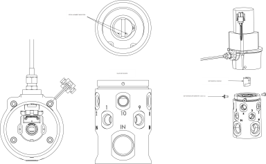
Removing the Motor / Encoder Assembly
-
Remove power from the fryer by unplugging from the power source.
-
Disassemble the fryer as required to access the port selector valve assembly.
NOTICE -
To avoid product damage, ensure the AIF board is completely disconnected from power when connecting harnesses.
Voltage spikes can damage the AIF board. No lights should be illuminated or flashing on the AIF board.
-
Disconnect both the 24 volt A/C motor connection and the AIF communication harness.
-
Remove the three reusable button cap screws connecting the motor/encoder to the selector valve and set aside.
-
Remove the old motor/encoder from the top of the port selector valve.
-
Remove the reusable motor/spool coupler from the port selector valve body and set aside.
Removing the Port Select Valve
-
Compare the new port selector valve part to the old port selector valve on the fryer and ensure they are the same, with the same port orientation.
The selector valves ports are numbered, ensure correct orientation when installing.
-
Note the locations of each flex tube by marking them with the port number where they are connected.
-
Disconnect each flex tube being careful not to bend them.
-
Note the port selector valves orientation on the fryer, and then loosen and remove the four nuts holding the base to the fryer.
-
Remove the port selector valve body being careful not to bend the flex tubes.
-
Note the location and orientation of each plug and connector fitting on the old port selector valve.
Installing the Port Select Valve
-
Loosen and remove each connector (plug), one at a time, from the old port selector valve and install them on to the new port selector valve in the correct (same) orientation. Use white Loctite #242 to ensure a good seal.
-
Install the new port selector valve on to the base, ensuring correct orientation.
-
Connect the flex tubes to the port selector valve and torque to 42 ft-lbs. DO NOT use Loctite on compression fittings.
-
On the port selector valve, align the spool so the spool alignment indicators point towards the number 10 (home) port.
-
Ensure the number 10 (home) port is fully open and if not, adjust as necessary.
Installing the Motor / Encoder Assembly
-
Place the motor/spool coupler back into the top of the port selector valve, making sure the male tang of the coupler engages the spool.
NOTICE -
To avoid product damage, ensure the AIF board is completely disconnected from power when connecting harnesses.
Voltage spikes can damage the AIF board. No lights should be illuminated or flashing on the AIF board.
-
Connect both the 24 volt A/C motor connection and the AIF communication harness.
-
Return power to the fryer by plugging into the power source.
-
Turn on the fryer’s main power switch. The motor/encoder spins twice then stops, which calibrates the motor/encoder.
-
Turn the main power switch off before continuing to prevent the motor/encoder from rotating out of position.
-
Place the new motor/encoder on to the port selector valve, making sure the motor/encoder’s male tang engages the female tang on the motor/spool coupler.
-
Apply Loctite #242 to the threads of the three button cap screws, and then install and torque to 34 in-lbs.
-
Test the valve by running a quick filter and visually inspecting for leaks.
-
Reassemble the fryer as required.
Related Content
Troubleshooting the Check JIB Message
Selector Valve Port Configurations
Replacing the Selector Valve Motor
Troubleshooting a Drain Pan Switch Failure
Troubleshooting a Change Pad Reminder XX hrs. Error
Troubleshooting an E-82D Selector Valve Error
CE Filter Motor Cover Retrofit
Bulk Dispose and Fill Retrofit
Retrofitting Adjustable Filter Pan Guide Rail
Reference
OFE 51X Software (without Connectivity)