Replacing the Drain Valve

|
To avoid electrical shock or property damage, move the power switch to OFF and disconnect power. |
Manually Operating
Should the actuation motor of a drain valve cease to operate, the drain valve can be operated manually as follows.
-
Support control panel bottom with one hand, loosen retaining screw at panel top, let panel slide down slightly to clear screw, push panel back up, then swing panel top out and down.
-
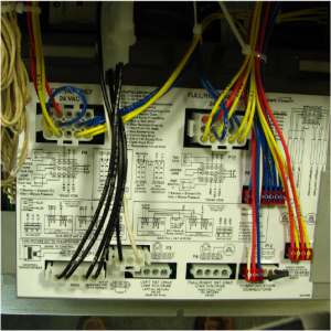
Trace wires from P12 on panel to vertical wall of controls area and separate required connector.
-
Using a 7/32 inch Allen wrench, loosen and unscrew two set screw until almost removed.
-
Using a flat blade screwdriver, pry motor from valve body.
-
Using a 1/4 inch or adjustable wrench, turn square stud shaft to operate valve ball.
-
Assemble in reverse order.
-
Support control panel bottom with one hand, swing panel top up about 90 degrees, let panel slide down slightly to clear screw, push panel top up to engage screw, then tighten screw.
Replacing
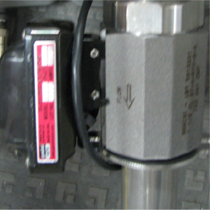
Each vat drain valve is opened and closed by an actuator. If oil won’t drain or pump back into a vat, the actuator may be faulty.
-
Support control panel bottom with one hand, loosen retaining screw at top, slide panel down slightly to clear screw, push panel bottom up, then switch panel top out and down.
-
Trace wires from P12 on panel to vertical wall of controls area and separate required connector.
-
From the rear of the fryer and using a 3/8 inch wrench, remove two nuts securing seal clamp to drain trough studs.
-
Grasp drain valve and motor assembly, turn assembly 1/8 turn (45°) counter clockwise (CCW) and slide assembly down so valve inlet clears vat drain tube.
-
Lift clamp up off of drain trough studs and maneuver valve and motor assembly with lower drain tube attached from under fryer.
-
Remove shims, O-ring and clamp from lower drain tube.
-
Using large slip joint pliers, turn lower drain tube 1/8 turn (45°) counter clockwise (CCW) and remove tube from valve.
-
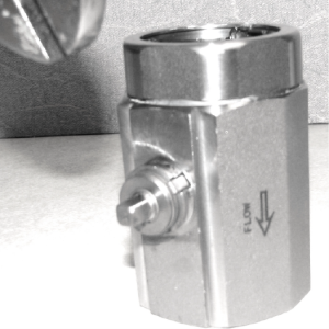
Remove O-rings from inlet and outlet sides of valve body.
-
Using a 7/32 inch Allen wrench, loosen and unscrew two set screws until almost removed.
-
Using a flat blade screwdriver, pry motor from valve body.
-
Reassemble in reverse order. Lubricate O-rings with cooking oil. Align “nubs” on drain tubes with notches in valve body, push tube into valve body and turn 1/8 turn (45°) clockwise (CW) to lock position.
Related Content
Replacing the Filter Motor Relay
Replacing the Filter Pan Switch
Replacing the Filter and JIB Lights
Repairing the Filter Pump and Motor Assembly
Replacing the Oil Level Probes
Adjusting the Drain Valve Actuator
Troubleshooting a Leaking Drain Valve
Troubleshooting an E-82 Error Code
LVE 20X Troubleshooting the Oil Not Pumping Error Code
Reference