Replacing the Oil Level Probes
The oil level probes monitor the oil level by temperature differences. If they becomes disabled, the display shows: “E-18A”= left probe; “E18-B”= right probe; “E18C”= both. Also, if any of the probes are out of calibration more than 10°F, or 10°C, the probe should be replaced. An Ohm check can be performed also.
(missing or bad snippet)Checkout
 | To avoid electrical shock or property damage, move the power switch to OFF and disconnect power. |
Support control panel bottom with one hand, loosen retaining screw at panel top, let panel slide down slightly to clear screw, push panel back up, then swing panel top out and down.
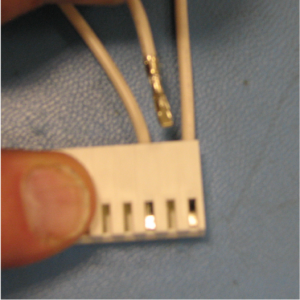
Pull probe connector from the control panel and locate the terminals in connector for probe being tested. Attach meter leads onto those terminals and refer to chart to determine if probe is good or not. (Probe wires are labeled, with #1 being the far left probe.)
Replacing
Reattach control panel and restore power to fryer.
Drain oil from vat.
Using a crosshead screwdriver, loosen retaining screw from control panel top and swing down the control panel.
Pull probe connector on left side of control panel.
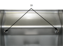
Follow lead wires through insulation down to desired probe.
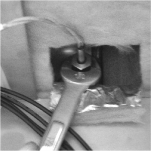
Using a 1/2 inch wrench, remove nut on compression fitting and remove oil level probe from vat.
Place connector on flat surface with the open side up.
Hold connector in place with one hand, use other hand to insert pocket knife blade or other small sharp tool into connector notch to depress metal locking tab.
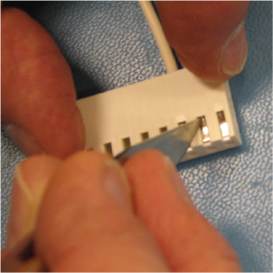
Continue to hold locking tab down and pull lead wire out of the rear of connector and remove probe from fryer.
Place nut and new ferule on new oil level probe and insert probe into compression fitting.
Locate temperature probe through vat wall.
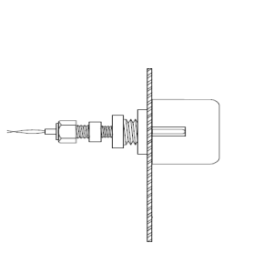
Place gauge against vat wall as shown.
Push temperature probe through until it makes contact with gauge.
(missing or bad snippet)Tighten temperature probe in place.
With locking tab up, insert pin into connector opening and visually check that tab is fully engaged. Fasten connector onto control panel.
Support control panel bottom with one hand, swing panel top up about 90 degrees, let panel slide down slightly to clear screw, push panel up to engage screw, then tighten screw.
Reconnect power to vat and fill vat with oil.
Related Content
Replacing the Filter Motor Relay
Replacing the Filter Pan Switch
Replacing the Filter and JIB Lights
Repairing the Filter Pump and Motor Assembly
Adjusting the Drain Valve Actuator
Troubleshooting a Leaking Drain Valve
Troubleshooting an E-82 Error Code
LVE 20X Troubleshooting the Oil Not Pumping Error Code
Reference