Replacing the Heating Elements
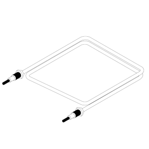
Description
Each fryer uses three heating element assemblies. Heating elements are available for 208, 220/240, or 440/480 voltage. Check the data plate inside the door to determine the correct voltage.
Maintenance Hint
If the oil's temperature recovery is very slow, or at a slower rate than required, this may indicate a defective heating element(s). An ohmeter will quickly indicate if the elements are shorted or open.
Checkout

|
To avoid electrical shock or property damage, move the power switch to OFF and disconnect power. |
-
Remove electrical power supplied to the fryer.
-
Remove the control panel and insert it in the slot above the door.
-
Perform ohm check on one heating element at a time, with wires disconnected from element. If resistance is not within tolerance, replace the element.
Heater P/N Power Voltage Resistance in Ohms (Cold)
18233-1 4500W 208 VAC 9±1 18233-2 4500W 230 VAC 11±1.5 18233-4 3750W 208 VAC 11±1.5 18233-5 3750W 220 VAC 12±2 18233-6 3750W 480 VAC 60±5 18233-7 4500W 480 VAC 50±4 18233-8 4500W 380 VAC 32±3.5
Replacement
-
Drain the oil.
-
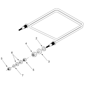
Remove the thermostat bulb holder from the heating element inside the vat.
-
Remove the heating element wires from the terminals by removing nuts and washers. Label each so it can be replaced in the same position on the new element.
-
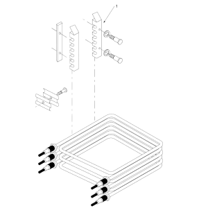
Loosen the bolts on the four element spreaders.
-
Slide the elements spreaders to the center of the heating element.
-
Remove the brass nuts and washers, which secure the ends of the elements through the vat wall.
-
Remove the heating elements from the vat as a group by lifting the far end and sliding them up and out toward the rear of the vat.
-
Install new heating elements with new rubber O-rings mounted on terminal ends, and spreaders loosely mounted in the center of the stacked elements.
-
Replace the heating elements, terminal end first at approximately 45º angle, slipping the terminal ends through the front wall of the vat.
-
Replace the brass nuts and washers on the heating element terminals. Tighten the brass nuts to the 30 foot lbs. of torque.
-
Move the element spreaders from the center of the element, into a poisiton which will spread each element apart evenly on all four sides, and tighten.
-
Replace the thermostat bulb holder on the top element, and position the bulb between the top and second element midway form side to side, and tighten the screw which holds the bulb in place.
-
Reconnect the wires to the appropriate terminal as labeled when they were removed.
-
Replace the front control panel.
-
Connect the power cord to the wall receptacle or close wall circuit breaker.
-
Check the heating elements as described in the Operator's manual.
-
Replace the oil in the vat.
Related Content
Replacing the High Temperature Limit Control
Calibrating The Standard Single Stage Thermostat
Replacing the Temperature Probe
Replacing the Heating Contactors
Replacing the Main Power Switch
Temperature Probe Gauge Instructions
Troubleshooting the PFE 500 and 561 E-5 Oil Overheating Error Code
Troubleshooting PFE 561 E-6 Temperature Probe Error Code
Troubleshooting PFE 561 E-10 High Limit Error Code
Troubleshooting PFE 500 and 561 E-26 Heat Amps Locked On Error Code
Troubleshooting an E-92 Error Code
Troubleshooting PFE 561 E-92 24V Current Limiter (Fuse) Trip Error Code
Troubleshooting Oil Melting or Heating Slowly
Troubleshooting PFE 500 W-1 Low Voltage Warning
Troubleshooting PFE 500 W-2 Slow Heating Warning
Troubleshooting PFE 500 W-3 Was Not Ready Warning
Troubleshooting PFE 500 W-4 Slow Cooking Warning
Troubleshooting PFE 500 W-5 Slow Cooking Warning
Troubleshooting PFE 500 W-6 Slow Cooking Warning
Troubleshooting PFE 500 W-9 Discard Product Warning
Reference