This is an electro-mechanical device that causes pressure to be held in the vat. The solenoid valve closes at the beginning of the Cook Cycle and opens automatically at the end of the Cook Cycle. If this valve should become dirty, or the Tn seat nicked, pressure will not build up. The fryer uses a 120 volt, 60 Hz coil 208/240 volt 60 hertz coil (50 hertz internationally).

|
To avoid electrical shock or property damage, move the power switch to OFF and disconnect power. |
Checking the Coils
-
Remove power from the fryer.
-
Remove the solenoid wires from the wire nuts which are found behind the control panel.
-
Check across wires.
| Volts/Phase | Results (Ohms) |
|---|---|
|
208/240 Volt, 60 Hertz |
150 Ohms |
|
208/240 Volt, 50 Hertz |
230 Ohms |
|
120 Volt, 60 Hertz |
50 Ohms |
Replacing the Solenoid
-
Remove the right side panel.
-
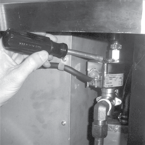
Remove the “tru-arc” retaining clip on top of coil housing.
-
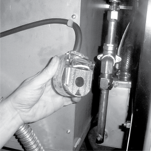
Remove the cover.
-
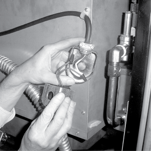
If only the coil is to be replaced, disconnect two coil wires at wire nuts in the coil housing. Remove coil, insert new coil, and connect wires at wire nuts. Assemble in reverse order of disassembly.
-
If the core-disc assembly is sticking due to buildup of oil, breading, and food particles, proceed with the following steps:
-
Unscrew the solenoid bonnet assembly from solenoid valve body.
-
Remove solenoid bonnet assembly and bonnet gasket.
-
Remove the core-disc assembly, core spring retainer, and the core spring.
-
Wash all these parts in hot water.
If the seals need to be replaced, proceed to Step 6; otherwise, assemble in reverse order of disassembly. Assemble valve core and blade with smooth side and rounded edge of blade toward the disc spring guide.
-
-
Repair kit, Part No. 17120, is available if any of the seals must be replaced. If one seal is defective, replace all seals.
Solenoid body must be removed from the fryer for replacement of seals.
-
Loosen wires on the strain relief and pull the wires through the relief.
-
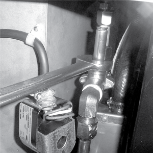
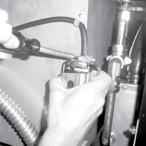
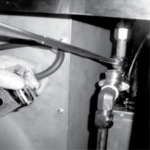
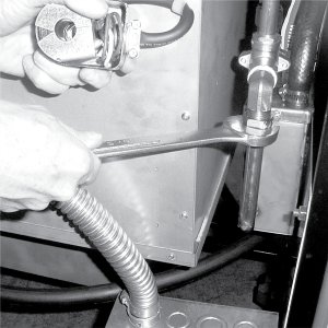
With the bonnet assembly and core-disc assembly removed, disconnect the two nut fittings. One connects the solenoid valve to the deadweight, the other is attached to the condensation tank.
-
Remove the elbows from the solenoid valve.
-
Remove the two adapter screws which attach the pipe adapter to the solenoid valve body.
-
Remove the disc spring, guide, and seat.
-
Clean the valve body.
-
Wet “O” ring around seat with water and insert O-ring assembly stide in valve through “IN” side of body. Use an eraser end of pencil and press in the seal until it snaps into place. Be careful not to mar or nick the seat.
The smallest nick can cause a pressure leak. Replace all O-ring seals that are in the parts kit and reassemble the valve.
-
If the complete valve is to be replaced, follow steps 1, 2, 3, 4, 5, 7, 8 and 9 in this section.
Related Content
Testing and Replacing the Power/Pump Switch
Replacing the Drain Microswitch
Replacing the Drain Valve and Extension
PFG-690/691 & OFG-390/391 Pump Motor Relay Kit
PFG 690 and 691 Installing Filter Rinse Hose
Operating Instructions for PFG-691/OFG-391 Direct-Connect Oil System
Direct-Connect Retrofit Instructions (For use on fryers after SN: 391-LH016JC & 691-LH029JC)
Troubleshooting the PFG 690 and 692 Oil Not Pumping Error Code
Reference
PFG 690 and 692 Inspection and Planned Maintenance