Applies to:
![]()
ALL CUSTOMERS
Operating Instructions for PFG-691/OFG-391 Direct-Connect Oil System
Kit number
14639
68499
Estimated Time
1 Hour to 1.5 Hours
-
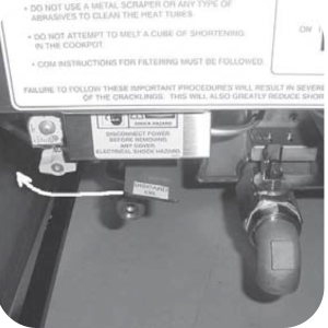
Connect the female quick disconnect, that is attached to the hose in the rear of the fryer, to the correct male quick disconnect at the wall.
-
Once attached, the hose can remain connected unless the fryer is moved.
-
Open filter valve and drop the oil from the vat into the filter pan.
-
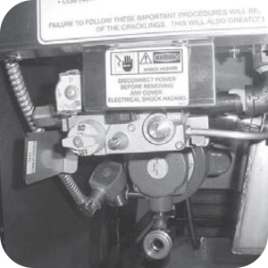
Once all oil is gone from vat move the paddle shaped handle labeled "discard oil" clockwise until it stops.
-
Turn the pump on / pump switch to the pump position. Oil is now pumped from the filter pan.
-
Once all the oil is out of the filter pan, turn the on / pump switch to the Off position.
-
Move the paddle-shaped handle back to original position.
-
Vat is now ready for fresh shortening.
Related Content
Testing and Replacing the Power/Pump Switch
Replacing the Drain Microswitch
Replacing the Drain Valve and Extension
PFG-690/691 & OFG-390/391 Pump Motor Relay Kit
PFG 690 and 691 Installing Filter Rinse Hose
Direct-Connect Retrofit Instructions (For use on fryers after SN: 391-LH016JC & 691-LH029JC)
Troubleshooting the PFG 690 and 692 Oil Not Pumping Error Code
I-Beam Cable Hole Plug Installation
FM08-502 8 Head Replacing KFC Control
FM08-481 8 Head Replacing the Control
Label Application and Location for the 8 Head Fryer
PFG-69X & OFG-39X Gas Valve Replacement Kit
Repositioning/Rewiring Air Valves for 220240V Model 690/390 fryers
Repositioning / Rewiring Air Valves for 120V Model 690/390 fryers
FM07-558 Gas Valve Replacement Kit
Conversion From C8000 Control to KFC SMS Control
Rear Cover Removal Instructions
Manifold Retrofit Kit Instructions
Replace Nylatron Slides on PFG 690 and 691
Installing Optional Crumb Basket
PFG 690 Stabilizer Retrofit Instructions
PFG 690/691 Ignition Module Kit
Mounting the OFG 390 and PFG 690 Vacuum Switch
Conversion From Standard 690 Control to S/M Control
PFG 690 and 691 Temperature Probe CE Instructions
Replace Gas Valve Assembly with Gas Valve and Solenoid Assembly
Replacing Gas Valve Assembly With Gas Valve and Solenoid Assembly
Air Switch Monitoring Retrofit Kit Instructions
PFG 691 C8000 Retrofit Instructions
PFG 690 and 691 Lid Cable Replacement
CE Gas Valve Adjustment Instructions
Replacing High Limit Thermocouple
Replacing the Drain Microswitch
Replacing the Drain Valve and Extension
Testing and Replacing the Power/Pump Switch
Replacing the Solenoid Below the Counter
Replacing the Solenoid Above the Counter
PFG 691 Attaching the Rinse Hose Instructions
Troubleshooting the PFG 691 Oil Not Pumping
Troubleshooting the PFG 691 E-15 Drain Open Error Code
Reference
PFG 690 and 692 Inspection and Planned Maintenance
PFG 690 and 692 KFC Annual Inspection Certification