Specifications
|
Height: |
61” (155 cm) |
|
Width: |
24” (61 cm) |
|
Depth: |
41¾” ( 107 cm) |
|
Floor Space: |
Approximately 7 sq. ft. (0.65 sq. m.) |
|
Vat Capacity: |
8 head of chicken (20 lbs) (9 kg) 130 lbs oil (59 kg) |
|
Electrical: |
120 VAC, 1 Phase, 50/60 Hz, 10 Amp, 3 Wire Service 230 VAC, 1 Phase, 50 Hz, 3 Wire Service |
|
Heating: |
Propane or Natural Gas; 100,000 btu/hr (105 MJ/hr) |
|
Shipping Weight: |
Approximately 935 lbs. (424 kg) |
|
Pressure: |
12 psi operating pressure (827 mbar) 14.5 psi safety relief pressure (999 mbar) |
| Vat Dimension side to side | 16 inches |
| Vat Dimension front to rear | 20.25 inches |
| Vat wall thickness | 14 gauge (0.075 in) (1.905 mm) |
Gas Specifications
The gas open fryer is factory available for either natural or propane gas. Check the data plate inside the left front door of the cabinet to determine the proper gas supply requirements. The minimum supply for natural gas is 7 inches water column (1.7 kPa) (17.0 mbar), and 10 inches water column (2.49 kPa) (24.9 mbar) for propane.

|
To avoid personal injury and/or property damage, use only type of gas specified on data plate. |
|
NOTICE - |
Gas pressure regulator has been set by manufacturer and should not be adjusted by user. |
The gas pressure regulator on the gas control valve is factory set as follows:
-
Natural: 3.5 inches water column (0.87 kPa) (8.72 mbar).
-
Propane 10.0 inches water column (2.49 kPa) (24.9 mbar).
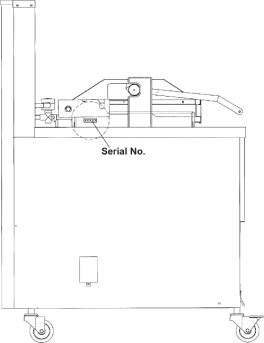
Data Plate Location
A data plate, located on the right side panel, gives the information of the type of fryer, serial number, warranty date, and other information pertaining to fryer.
In addition, the serial number is stamped on the outside of the counter top.
Related Content
Information about the 690 and 692 Fryers
Installing the 690 and 692 Fryers
Operating the 690 and 692 Fryers
Programming the 690 and 692 Fryers
Training on the 690 and 692 Fryers
Troubleshooting the 690 and 692 Fryers
Cleaning the Safety Relief Valve
FM08-502 8 Head Replacing KFC Control
FM08-481 8 Head Replacing the Control
Conversion From C8000 Control to KFC SMS Control
Conversion From Standard 690 Control to S/M Control
PFG 691 C8000 Retrofit Instructions
Troubleshooting the SMS Control Online Projection System (OPS) Connection
Troubleshooting the C8000 Open Fryer Message
Troubleshooting the PFG 690 and 692 E-41 Control Programming Lost Error Code
Replacing the High Temperature Limit Control
Replacing the Temperature Probe
Replacing the Gas Control Valve
Replacing the Flame Sensor Assembly
Replacing the Ignitor Assembly
Replacing the Ignition Modules
Replacing High Limit Thermocouple
PFG-69X & OFG-39X Gas Valve Replacement Kit
Repositioning/Rewiring Air Valves for 220240V Model 690/390 fryers
Repositioning / Rewiring Air Valves for 120V Model 690/390 fryers
FM07-558 Gas Valve Replacement Kit
Manifold Retrofit Kit Instructions
PFG 690/691 Ignition Module Kit
Mounting the OFG 390 and PFG 690 Vacuum Switch
PFG 690 and 691 Temperature Probe CE Instructions
Replace Gas Valve Assembly with Gas Valve and Solenoid Assembly
Replacing Gas Valve Assembly With Gas Valve and Solenoid Assembly
Air Switch Monitoring Retrofit Kit Instructions
CE Gas Valve Adjustment Instructions
Troubleshooting the PFG 690 and 692 E-4 Control Overheating Error Code
Troubleshooting the PFG 690 and 692 E-5 Oil Overheating Error Code
Troubleshooting the PFG 690 and 692 E-6 Temperature Probe Error Code
Troubleshooting the PFG 690 and 692 E-10 High Limit Error Code
Testing and Replacing the Power/Pump Switch
Replacing the Drain Microswitch
Replacing the Drain Valve and Extension
PFG-690/691 & OFG-390/391 Pump Motor Relay Kit
PFG 690 and 691 Installing Filter Rinse Hose
Operating Instructions for PFG-691/OFG-391 Direct-Connect Oil System
Direct-Connect Retrofit Instructions (For use on fryers after SN: 391-LH016JC & 691-LH029JC)
Troubleshooting the PFG 690 and 692 Oil Not Pumping Error Code
Replacing the Lid Counterweight Cables
Calibrating and Cleaning the Pressure Gauge
I-Beam Cable Hole Plug Installation
Replace Nylatron Slides on PFG 690 and 691
PFG 690 and 691 Lid Cable Replacement
Label Application and Location for the 8 Head Fryer
Rear Cover Removal Instructions
Installing Optional Crumb Basket
PFG 690 Stabilizer Retrofit Instructions
Reference
PFG 690 and 692 Inspection and Planned Maintenance