Applies to:
![]()
ALL CUSTOMERS
PFG-690/691 & OFG-390/391 Pump Motor Relay Kit
5/16 in. Socket or nut driver
Crosstip head screwdriver
Wire cutters
Wire strippers
Kit number
140012
Estimated Time
1 Hour

|
To avoid electrical shock or property damage, move the power switch to OFF and disconnect power. |
These are the installation instructions of replacing pump motor relay in models PFG-690/691’s and OFG-390/391’s.
-
Remove power from unit.
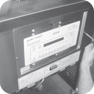
-
Use a crosstip head screwdriver or a cordless drill to remove the front control panel.
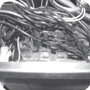
-
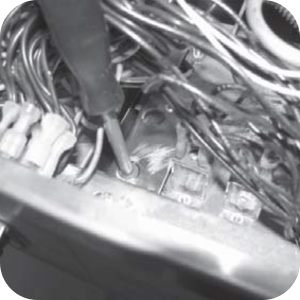
Use a 5/16 in. socket or nutdriver to remove the nuts securing the left pump motor relay. Leave wires connected to relay and pull relay from studs.
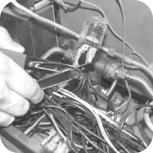
-
Locate wire terminals in kit. Cut the wires as close to the relay terminals as possible, strip wires and crimp on new terminals, one set at a time.
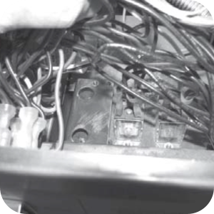
-
Locate relay bracket in kit and place inside control panel area, lining-up the studs, with the holes in the bracket (large holes on top).
-
Use a 5/16 in. socket or nutdriver to secure the bracket to the unit with the nuts provided in the kit.
-
Connect wires to the relay. This wiring allows the air solenoid to be used when needed, instead of constantly in use.
-
Use a crosstip head screwdriver to secure the relay to the bracket with the screws provided in the kit.
-
Replace control panel and restore power to the fryer.
-
Fryer is now ready for use.
Related Content
Testing and Replacing the Power/Pump Switch
Replacing the Drain Microswitch
Replacing the Drain Valve and Extension
PFG 690 and 691 Installing Filter Rinse Hose
Operating Instructions for PFG-691/OFG-391 Direct-Connect Oil System
Direct-Connect Retrofit Instructions (For use on fryers after SN: 391-LH016JC & 691-LH029JC)
Troubleshooting the PFG 690 and 692 Oil Not Pumping Error Code
I-Beam Cable Hole Plug Installation
FM08-502 8 Head Replacing KFC Control
FM08-481 8 Head Replacing the Control
Label Application and Location for the 8 Head Fryer
PFG-69X & OFG-39X Gas Valve Replacement Kit
Repositioning/Rewiring Air Valves for 220240V Model 690/390 fryers
Repositioning / Rewiring Air Valves for 120V Model 690/390 fryers
FM07-558 Gas Valve Replacement Kit
Conversion From C8000 Control to KFC SMS Control
Rear Cover Removal Instructions
Manifold Retrofit Kit Instructions
Replace Nylatron Slides on PFG 690 and 691
Installing Optional Crumb Basket
PFG 690 Stabilizer Retrofit Instructions
PFG 690/691 Ignition Module Kit
Mounting the OFG 390 and PFG 690 Vacuum Switch
Conversion From Standard 690 Control to S/M Control
PFG 690 and 691 Temperature Probe CE Instructions
Replace Gas Valve Assembly with Gas Valve and Solenoid Assembly
Replacing Gas Valve Assembly With Gas Valve and Solenoid Assembly
Air Switch Monitoring Retrofit Kit Instructions
PFG 691 C8000 Retrofit Instructions
PFG 690 and 691 Lid Cable Replacement
CE Gas Valve Adjustment Instructions
Replacing High Limit Thermocouple
Replacing the Drain Microswitch
Replacing the Drain Valve and Extension
Testing and Replacing the Power/Pump Switch
Replacing the Solenoid Below the Counter
Replacing the Solenoid Above the Counter
PFG 691 Attaching the Rinse Hose Instructions
Troubleshooting the PFG 691 Oil Not Pumping
Troubleshooting the PFG 691 E-15 Drain Open Error Code
Reference
PFG 690 and 692 Inspection and Planned Maintenance
PFG 690 and 692 KFC Annual Inspection Certification