Applies to:
![]()
ALL CUSTOMERS
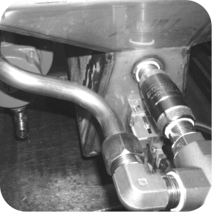
PFG 690 and 691 Installing Filter Rinse Hose
Adjustable wrench
Crosstip head screwdriver
Hi-temp pipe thread sealant
Pipe Wrench
Kit number
14765
14996
Estimated Time
30 Minutes

|
TO AVOID INJURY, PROPERTY DAMAGE, OR EXPLOSION, BEFORE REPLACING STARTING THIS PROCEDURE, DO THE FOLLOWING:
|

|
Burn Risk Using PPE, remove hot oil from fryer before performing procedure or personal injury may occur. |
-
Disconnect power, and gas from fryer. Drain oil from fryer.
-
Use a crosstip head screwdriver to remove left side panel.
-
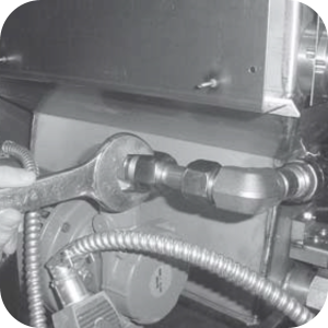
Use an adjustable wrench to loosen the two fittings to the pump return line.
-
Remove the short tube assembly from the fryer. If necessary, loosen the filter motor mounting bolts.
-
Unscrew the check valve assembly form the elbow.
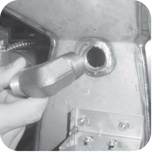
-
Unscrew the elbow from the vat.
-
When assembling components apply high temperature pipe thread sealant to the threads of all fittings except the compression threads of the 90º ¾” male elbow.
-
Screw one of the ¾” close nipples into the vat.
-
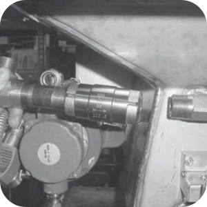
Fit the ¾” check valve over the ¾” close nipple.
-
Insert the other ¾” close nipple into the other side of the ¾” check valve.
-
Fit the ¾” diverter valve over the ¾” close nipple. Ensure the opening opposite the diverter valve handle is on the pump side of the vat.
-
Insert the ¾” bushing into the ¾” diverter valve.
-
Insert the 3/8” close nipple into the ¾” bushing.
-
Fit the 3/8” male disconnect over the 3/8” close nipple.
-
Insert the tapered thread side of the 90º ¾” male elbow into the side opening of the ¾” diverter valve.
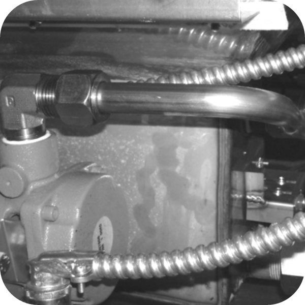
-
Install the oil return tube between the pump elbow and 90º ¾” male elbow.
-
Install x2 1/4” elbows on the solenoid valve.
-
Position elbow opening to the back of the fryer.
-
Tighten all fittings with a wrench.
-
If the filter pump motor mounting bolts are loose, they must be tightened at this time. Lift up on the motor when tightening the bolts or the motor will interfere with the filter pan.
Related Content
Testing and Replacing the Power/Pump Switch
Replacing the Drain Microswitch
Replacing the Drain Valve and Extension
PFG-690/691 & OFG-390/391 Pump Motor Relay Kit
Operating Instructions for PFG-691/OFG-391 Direct-Connect Oil System
Direct-Connect Retrofit Instructions (For use on fryers after SN: 391-LH016JC & 691-LH029JC)
Troubleshooting the PFG 690 and 692 Oil Not Pumping Error Code
I-Beam Cable Hole Plug Installation
FM08-502 8 Head Replacing KFC Control
FM08-481 8 Head Replacing the Control
Label Application and Location for the 8 Head Fryer
PFG-69X & OFG-39X Gas Valve Replacement Kit
Repositioning/Rewiring Air Valves for 220240V Model 690/390 fryers
Repositioning / Rewiring Air Valves for 120V Model 690/390 fryers
FM07-558 Gas Valve Replacement Kit
Conversion From C8000 Control to KFC SMS Control
Rear Cover Removal Instructions
Manifold Retrofit Kit Instructions
Replace Nylatron Slides on PFG 690 and 691
Installing Optional Crumb Basket
PFG 690 Stabilizer Retrofit Instructions
PFG 690/691 Ignition Module Kit
Mounting the OFG 390 and PFG 690 Vacuum Switch
Conversion From Standard 690 Control to S/M Control
PFG 690 and 691 Temperature Probe CE Instructions
Replace Gas Valve Assembly with Gas Valve and Solenoid Assembly
Replacing Gas Valve Assembly With Gas Valve and Solenoid Assembly
Air Switch Monitoring Retrofit Kit Instructions
PFG 691 C8000 Retrofit Instructions
PFG 690 and 691 Lid Cable Replacement
CE Gas Valve Adjustment Instructions
Replacing High Limit Thermocouple
Replacing the Drain Microswitch
Replacing the Drain Valve and Extension
Testing and Replacing the Power/Pump Switch
Replacing the Solenoid Below the Counter
Replacing the Solenoid Above the Counter
PFG 691 Attaching the Rinse Hose Instructions
Troubleshooting the PFG 691 Oil Not Pumping
Troubleshooting the PFG 691 E-15 Drain Open Error Code
Reference
PFG 690 and 692 Inspection and Planned Maintenance
PFG 690 and 692 KFC Annual Inspection Certification