Replacing the Relay
crosshead screwdriver

|
To avoid electrical shock or property damage, disconnect power before installing or servicing equipment. A qualified technician must perform the service procedures. |
-
Using a crosshead screwdriver, remove the four screws securing the front panel.
-
With power reapplied, let unit start heating up, or enter the Tech Mode in Special Program Mode and check the relays in the output test. (See T-18 in the Tech Mode.)
-
With the component energized (example: air heaters), 0 volts should show on the output side of the relay, and 12 volts on the input side.
-
With the component not energized, 208 or 240 volts should show on the output side of relay, and 0 volts on input.
-
If voltage varies from steps 4 and 5, remove power to unit, pull input wires from relay and place leads of meter onto input wires. Reapply power to unit. When unit is running, the input wires to relay should show 12 vdc volts. If this proves true, the relay is faulty and continue onto step 7.
-
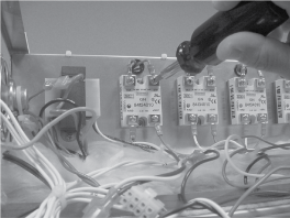
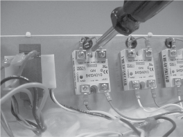
Label wires and then remove wires from relay using a crosshead screwdriver.
-
Using a crosshead screwdriver, remove the 2 screws securing the relay and remove relay from unit.
-
Coat the back of the relay with the thermal joint compound.
Failure to use the thermal joint compound will shorten the life of the relay.
-
Install new relay in reverse order and unit is now ready for use.
|
|
SHOCK HAZARD To avoid electrical shock, perform relay checks or transformer checks as described as instructions. |
The following checks are performed with the wall circuit breaker closed and the main power switch in the ON position. Extreme caution should be taken. Make connections before applying power, take reading, and remove power before removing meter leads, or electrical shock could result.
Related Content
Replacing the Control Panel or PC Board
Replacing the Fuse and Fuse Holder
HHC 99X Troubleshooting E-4 CPU Overheating Error Code
HHC 99X Troubleshooting E-41 System Data Lost Error Code
Replacing the Air Temperature Probe
Replacing the Food Probe Receptacle
Replacing the Air Heater High Limit
Replacing the Vent Motor Microswitch
HHC 99X Troubleshooting the E-5 Air Temp Sensor Failed Error Code
HHC 99X Troubleshooting the E-80 Vent Stuck or Bad Switch Error Code
Installing HHC Vent Motor Retrofit
Reference