Replacing Safety Relief Valve

|
To avoid personal injury or property damage, before starting this procedure, move the main power switch to the off position. Disconnect the main circuit breakers at the circuit breaker box or unplug service cord from wall receptacle. |
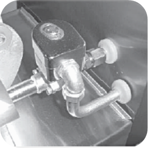
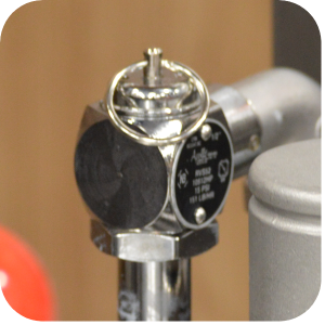
Solenoid Valve
This is an electromechanical device that causes pressure to be held in the vat. The solenoid valve closes at the beginning of the cook cycle and is opened automatically by the timer at the end of the cook cycle. If this valve should become dirty or the teflon seat nicked, pressure will not build up. The fryer uses a 120 volt, 60 Hz coil.
Coil Check Procedure
Remove wires from terminals 73 and 72. Check across solenoid wires.
| Test Volts / Phase | Results |
|---|---|
| 24 volt | 2.2 Ohms |
| 120 volt 60 Hz | 50 Ohms |
| 208-240 volt 60 Hz | 150 Ohms |
| 208-240 volt 50 Hz | 245 Ohms |
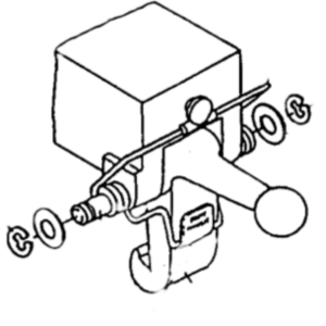
Replacement
Remove Tru-Arc retaining clip on top of the coil housing.
Remove the nameplate and cover.
If only the coil is replaced, disconnect two coil wires at the wire nuts in the coil housing.
Remove the coil from the housing.
Replace name plate, cover and Tru-Arc clip, if the complete solenoid or seal are being replaced. Wires can be connected in any order.
|
NOTICE - |
The wires may be connected in any order. |
|
NOTICE - |
Remove the solenoid body from fryer to replace seals. |
|
NOTICE - |
The smallest nick can cause a pressure leak. Replace all O-ring seals, found in the parts kit. Reassemble the valve. |
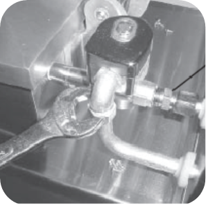
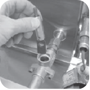
If the complete solenoid or seal are being replaced, then loosen the nut on the 1/2 in. connector and pull piping conduit from the valve case. Leave enough slack to remove the coil housing and yoke.
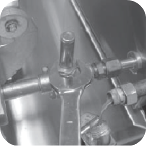
If the core-disc assembly is sticking due to buildup of oil, breading and or food particles. Unscrew the solenoid bonnet assembly from the solenoid valve body.
-
Unscrew the solenoid bonnet assembly from the solenoid valve body.
-
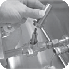
Remove the solenoid bonnet assembly and bonnet gasket.
-
Remove the core-disk assembly, core spring retainer, and the core spring.
-
Wash all parts in soap and hot water.
If replacing Teflon seals, or complete valve, a repair kit Henny Penny Part No. 17120 is available if any of the seals need to be replaced. If any one seal is defective, all seals should be replaced.
Remove solenoid body form fryer to replace seals.
-
Remove back cover.
-
Loosen both conduit and exhaust fittings.
-
Remove nipple from solenoid body.
-
Unthread body from fryer.
-
A new solenoid can now be placed on the fryer, and reassembled in reverse order. Unless seals need to be changed.
To change seals, remove two adapter screws which attach the pipe adapter to the solenoid body.
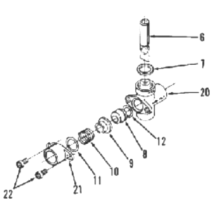
Remove the disc spring, guide, and seat.
Clean the valve body.
Wet O-ring around the seal with water and insert O-ring assembly (flat side first) in valve, through the IN side of body.
Use a pencil eraser, and press in Teflon seal until it snaps into places. Ensure not to mark or nick the seal. The smallest nick can cause a pressure leak.
Replace all O-ring seals and reassemble valve.
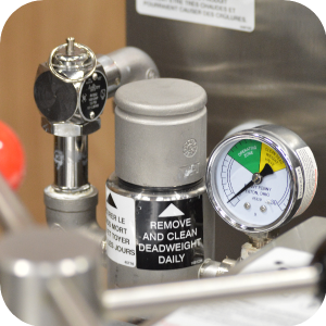
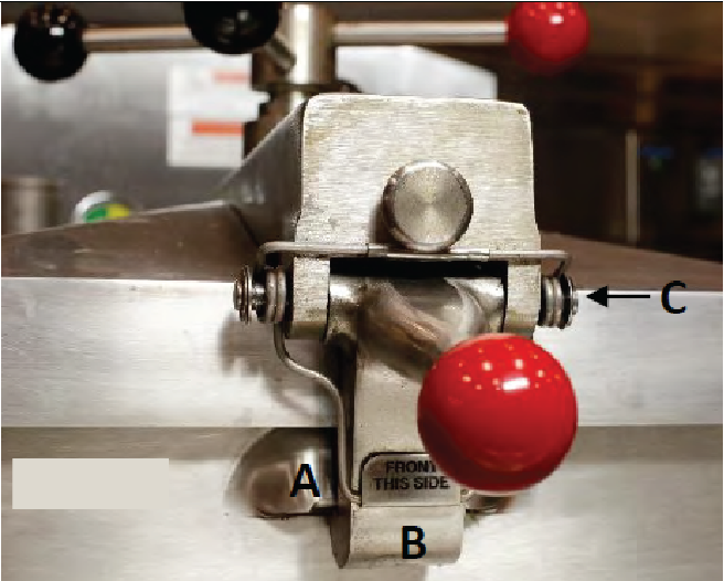
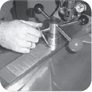
Deadweight Valve
|
|
To avoid severe burns, do not remove deadweight cap while operating fryer. |
|
|
To avoid severe burns, do not tamper with safety relief valve while operating fryer. |
|
|
Burn Risk To avoid serious personal injury, keep body parts away from safety valve exhaust. |
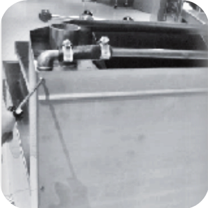
The Deadweight valve and safety relief valve are located side-by-side at the back of the unit. The valve next to the pressure gauge is operating control valve and the other valve is a 14 1/2 lb. safety relief valve. Valves will not work properly when Operating Zone is indicated on the gauge by the pointer. The gauge pointer should not normally exceed the operating zone. At 14 1/2 psi the safety relief valve opens to release stem pressure from the vat.
Cleaning Steps
-
Clean the deadweight valve at the end of each day.
-
Turn the fryer off and release all the pressure.
-
Open the lid and then remove the deadweight valve cap and deadweight.
-
Place both the cap and weight in hot detergent water and clean. Ensure to thoroughly clean inside cap, weight seal and around the deadweight orifice.
-
Rinse thoroughly with hot water.
-
Dry parts and replace immediately to prevent damage or loss.
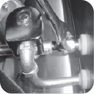
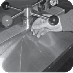
Removal and Cleaning of Safety Relief Valve
|
|
To avoid severe burns, do not tamper with safety relief valve while operating fryer. |
|
|
To avoid serious personal injury, do not tamper with safety relief valve. Tampering with this valve will void agency approvals and appliance warranty. |
This valve is factory preset to open at 14½ psi. (999 mbar).
|
NOTICE - |
Do not use a pipe wrench. Use thread sealant sparingly. |
The safety relief valve should be cleaned once a year.
-
Open the lid and then remove the deadweight valve cap and deadweight. Do not use a pipe wrench and use thread sealant sparingly.
-
Use a wrench to loosen the valve from the pipe elbow, turn counterclockwise to remove.
-
Clean the inside of the pipe elbow with hot detergent.
-
Immerse the safety relief valve in a soap water solution for 24 hours. Use a 1:! dilution rate. The valve cannot be disassembled. The factory present is to open at 14 1/2 pounds of pressure. If it does not open or close, it must be replaced.
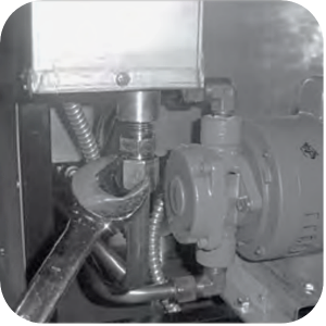
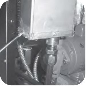
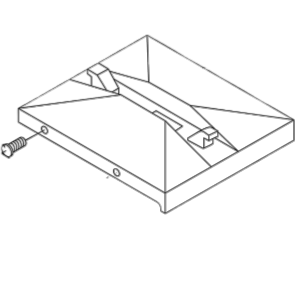
Condensation Box Bottom Removal
-
Loosen fitting at the bottom of the box.
-
Use a cross-tip screwdriver to remove 4 screws securing the bottom of the box and pull bottom from assembly.
-
Clean outlet hole in box bottom and check condensation tube for clogs. Clean if necessary.
-
Reinstall box bottom and condensation line.
-
Seal box bottom with silicone sealant and unit is now ready for operation.
Lid Cover Assembly
Description
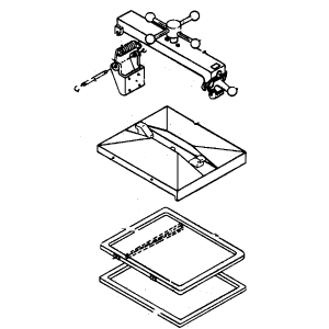
In general the spindle, the limit stop, the cover, the hinge, the inner and the reversible gasket comprise the lid cover assembly.
Lid Cover Removal
The lid cover is easily removable for cleaning or service.
-
Close the lid cover and turn spindle counterclockwise until it stops.
-
Pull the lid release pin on front of the crossbar, lift the latch and raise the crossbar.
-
The cover can now be removed from vat.
Lid Cover Installation
-
Place the lid cover on the vat.
-
Thread the spindle counterclockwise until it is completely extended.
-
Align the rear retaining hook on lid cover in the center slot of the crossbar.
-
Push the crossbar down and pull out on lid release pin.
-
Push the lid to rear of vat and latch the crossbar to the lid cover.
-
Release the pin.
-
Check that lid cover is fastened properly before raising.
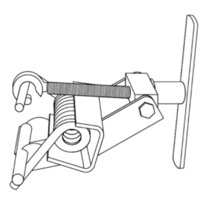
Lid Hinge Spring
The hinge spring needs to be replaced if it is broken, cracked or loses tension. A special spring installation tool which greatly simplifies this procedure is available from the factory.
-
Pull out the retaining pin knob on the front of the crossbar to release lid cover.
-
Lift the cross bar up and away from the lid.
-
Remove Tru-Arc locks and hinge pin if the spring is broken. If the spring is not broken, use spring tool to remove the Tru-Arc lock and hinge pin
-
Remove the broken spring.
-
The new spring is placed in the loading tool so that the spring coil is laying in the U-shaped center of the tool. The perpendicular shaft is placed in the stationary hook of the tool. The parallel shaft is placed so the adjustable hook will tighten it down.
-
Tighten the handle on the tool as far as it will go.
-
Place the spring (loaded in the tool) into position so that U-shaped center of the tool is towards the front of fryer and the tool handle is toward the top of the fryer.
-
Replace hinge pin and Tru-Arc locks. Loosen and remove the tool.
-
Reinstall the lid
Latch Spring Installation

|
.To avoid severe burns and injuries, ensure the lid is secure during a cook cycle. The latch spring must be in good working order and properly installed. If latch spring is weak, broken or mounted backwards, it will provide little force against the latch. |
The latch on the crossbar must have the external coil-type latch spring mounted on latch pin. If a latch spring is weak or broken, it must be replaced with a new spring. The part number is 33480.
-
Replace the crossbar from the lid.
-
With the crossbar in the upright position, remove one of the two Tru-Arc rings from latch pin.
-
Tap out pin from latch while grasping latch, and remove latch and latch spring.
-
Install new latch spring with coils of spring extending forward.
-
Secure spring in place with Tru-Arc ring.
Lid Liner
-
Remove the four lid screws.
-
Use a thin blade screwdriver to pry lid from the cover.
-
Clean the liner and the inside of the cover. Replace the liner and screws.
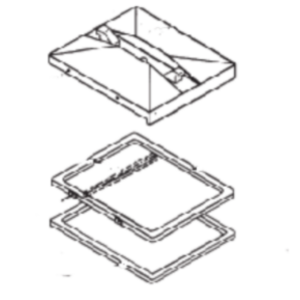
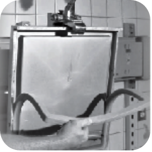
Reversing The Lid Gasket
|
NOTICE - |
The seven o'clock position is only to allow slight additional turning of the spindle to relieve any side pressure that could hold the locking pin in the locking collar after all pressure has been released from the vat. |
The gray rubber gasket surrounding the inside of lid is designed to be reversed. Henny Penny recommends that this be done on quarterly basis.
Purpose
Because of heat expansions and the pressure used for the cooking process, the gasket is constantly under extreme stress. Reversing the lid gasket on a quarterly basis will help to assure that the fryer will not lose pressure through leakage.
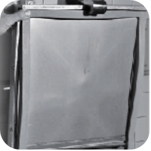
Process
-
There are two lid liner screws on either side of the lid cover. Back these four screws out about 1/2 in.
-
Open lid and using a thin blade screwdriver, pry out the gasket at the corners. Remove the gasket.
-
Clean the gasket and gasket seal with hot water and cleaning detergent. Rinse with clean hot water.
-
Install the gasket with the good side facing out. Tighten the four screws.
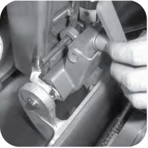
Lid Limit Stop Adjustment
The lid limit stop, with proper adjustment, prevents unnecessary over tightening of the spindle, and as a result, extends the life of the lid gasket.
-
Loosen the Allen wrench screws on the bottom of the collar of the limit stop assembly.
-
Turn the inner collar of the limit stop clockwise as far as possible. Find the small hole in the inner collar and use a small Allen wrench or Cross tip head screwdriver to help in turning the collar.
-
Close lid and turn spindle until lid gasket meets the top of the vat rim.
-
From this position, turn spindle at least 3/4 of a turn, but not over one full turn.
-
After rotating spindle to this point, slightly extend the spindle past this position. The spindle should then be at the seven o'clock position. Note it may be necessary to remove knobs and change their position in order to align the red knob with the red knob on the lid cover latch. When in the normal operating position, both red knobs should be aligned.
|
NOTICE - |
Check the gasket for any tears or nicks. Replace damaged gaskets. |
-
Adjust the limit stop by turning it clockwise until it stops against the bottom hub of the spindle.
-
Tighten Allen set screws.
-
If the lid cover fails to seal properly, steam will escape around the gasket during the frying operation. The limit should be readjusted. This time turn the spindle screw one full turn after the initial contact of the lid gasket against top of the vat rim.