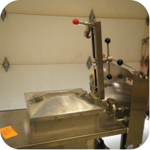
4 Head PFE 500/ PFG 600 Removing the Lid
3/8 in. hex key
3/16 in. hex key
9/16 in. socket
Adjustable wrench
Crosstip screwdriver
Drill gun
Flat head screwdriver
Thread sealant
Pipe wrench
Wire cutters
Kit number
140358
Estimated Time
45 Minutes to 1 hour

|
To avoid electrical shock or property damage, move the power switch to OFF and disconnect power. |
-
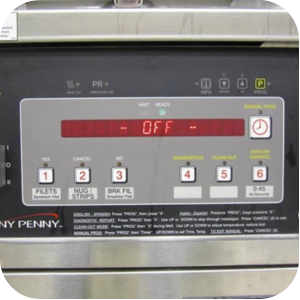
While the fryer is still connected to a power source turn the power switch on the fryer to the OFF position.
-
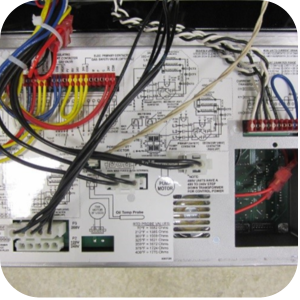
Use a crosstip screwdriver to remove the four screws securing the control board. Hang the screws on the bezel for support.
-
Use a crosstip screwdriver to remove the control access cover.
-
Reflashing Henny Penny PFE Controllers:
-
Kanda Programmer Instructions.
-
Replace the access cover.
-
Close the control panel and secure in place.
-
With the power switch still in the OFF position press and hold the down arrow while turning the power switch to COOK.
-
The control will show "MFG MODE" then "MFG" and "ENTER CODE".
-
The control will show "1=CNTRL 2=FRYER". Press the illuminated number 2 to enter "FRYER TEST".
-
Press and hold the "1" button to ensure the display reads "HP P/N=97729 A". If it does not stop, remove all the programmer connections and repeat.
-
Tap the left arrow three times until "FT-20 INIT" shows on display.
-
Press and hold the down arrow button.
-
The control shows "TOT INIT IN 3..2..1.." then will flash "INIT".
-
Once done, initializing the display will read "INIT DONE".
-
Turn the power switch to the OFF position and disconnect power from the unit.
-
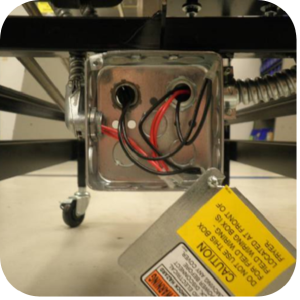
Use a crosstip screwdriver and remove the top screw in the junction box located in the bottom-back of the unit.
-
Remove junction box cover and set aside.
-
Use wire cutters to cut the red wires labeled P1-1 and P2-1. Ensure to cut as close to the wire connectors as possible.
-
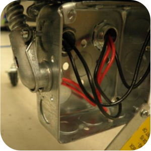
Cap wires P1-1 and P2-1 using the closed end slices supplied in kit.
-
Use a flat-head screwdriver to loosen the conduit connector and remove the conduit connector from the junction box.
-
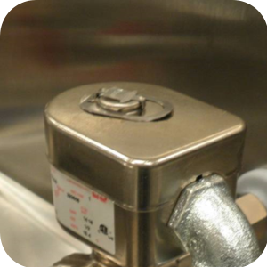
Use a flat-blade screwdriver to remove the top clip on the solenoid valve.
-
Remove the cap of the solenoid valve.
-
Use an adjustable wrench to loosen the compression nut.
-
Remove the solenoid from the stem.
-
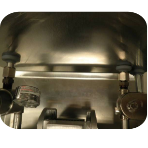
Use an adjustable wrench to loosen the compression nuts at the dead weight and solenoid valve located on the back of the pot.
-
Use an adjustable wrench to disconnect the condensation line from the steam box.
-
Use a crosstip screwdriver to remove the screws securing the rear shroud cover and screws.
-
Discard the rear shroud cover.
-
Use a crosstip screwdriver to remove the screws that secure the rear shroud to the fryer frame.
-
Remove the entire rear shroud with the steam box and the solenoid coil and discard.
-
Note, grommets, compression nuts and rubber sleeve fittings can be discarded.
-
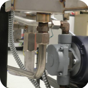
Use an adjustable wrench to remove the dead-weight assembly from the elbow fitting and discard.
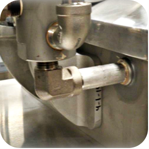
-
Use a pipe wrench to remove the pipe nipple from the vat wall.
-
Use a pipe wrench to remove the pipe nipple along with all the solenoid valve components from the vat wall and discard.
-
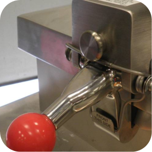
Pull the lid retaining pin located on the front of the cross arm.
-
With the retaining pin pulled, lift up on the center bar latch to disengage the bar from the lid.
-
Rotate the center bar up and off of the lid assembly.
-
Discard lid assembly.
-
Use a 9/16 in. socket to remove the four screws that secure the center arm hinge to the unit.
-
Discard center bar assembly, hinge and screws.
-
Use the new plugs from the kit and apply thread sealant.
-
Thread the new plugs into the holes on the vat wall where the dead-weight and solenoid was removed. Tighten with a 3/8 in. hex-key
-
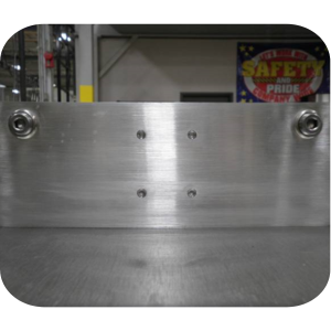
Thread the four new set screws into the vat wall where the center bar was removed.
-
Tighten with a 3/16 in. hex-key.
-
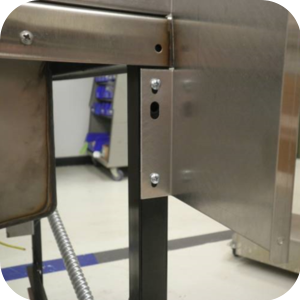
Secure the new rear shroud to the frame with the four self-tapping screws.
-
Use a crosstip screwdriver to remove the condensation tube and bracket from the frame and discard.
-
Remove the condensation pan and discard.
-
Clean the exterior of the control with a foaming degreaser.
-
Use the new labels from the kit to place onto the control.
-
Center the 0:45 label on the right side of the control and use the 2 menu labels to completely cover the old menu items underneath the 1-2-3 and 4-5-6 buttons.
Related Content
Replacing the Lid Cover Assembly
Replacing the Lid Latch Spring
Replacing the Safety Relief Valve
Replacing the Deadweight Valve
Pressure Assist Features and Function
Replacing the Pressure Regulation and Exhaust Components
Pressure Assist Kit Installation
Troubleshooting an W-1 Low Voltage Error Code
Direct connect oil system operating instructions
Electronic C2000 Simple Control Retrofit Kit
RLink programming instructions
PFE 500/PFG 600 Wi-Fi Verification and Troubleshooting Instructions
PFE 500/PFG 600 Hybrid Control Installation Instructions
2nd Generation Radio for SMS: Hardware Installation
2nd Generation Radio for SMS: Software Update
FM08-748 2nd Generation Radio for SMS: Troubleshooting
Instructions for Fryer Control Replacement Kits
SMS 20 Auto Polish Programming Instructions
Temperature Probe Gauge Instructions
CFA PFE 500 Hybrid Wi-Fi Status Check
Replacing Condensation Box Assembly
Replacing the Deadweight Valve
Pressure Assist Features and Function
Installation of PFG 600 and PFG 600 SSI FM07-366 Electromechanical to C1000 Retrofit
PFG 600 SSI Electronic C1000 to C8000 Retrofit Kit
Direct connect retrofit PFG 600
Direct connect retrofit PFG-600
PFG 600 Ignition Module Retrofit Kit
PFG 600 SSI Fryers Gas Valve Replacement Kit
SAE Thread Filter Pump Installation
Pre VA SAE Thread Filter Pump Installation
Hybrid Control and Wi-Fi Installation
Reference
PFE 500 and 561 Inspection and Planned Maintenance
PFE 500 KFC Annual Inspection Certification