Spring Tool Operation Kit
Punch
Hammer
Needle-Nose Pliers
Cut Off Wheel
Spring Loading Tool
Lid Hinge Pin
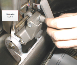
Tru-Arc Locks (2)
Hinge Spring
Kit number
14960
Estimated Time
30 Minutes

|
Only perform this procedure when the unit is cool or severe burns may result. |
Below are the steps for replacing the lid hinge spring and determining if lid hinge pin needs replacement.
-
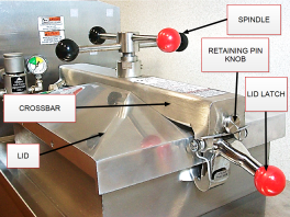
Completely unscrew the spindle by turning it counterclockwise.
-
Pull out the retaining pin knob on the front of the crossbar to separate the lid and crossbar.
-
While pulling out the retaining pin knob, lift up the lid latch to separate the crossbar from the lid. Then, lift and remove the lid from the fryer and set aside.
-
Cover the vat to prevent anything from falling into the oil.
-
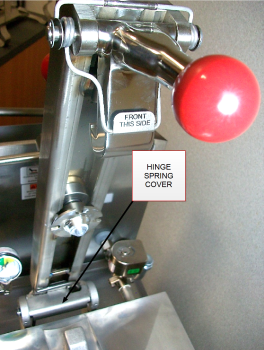
Remove hinge spring cover.
-
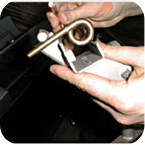
Use Spring Loading Tool to fully loosen spring for instances where the spring is not broken.
-
Use pliers to remove a Tru-Arc Lock from one side.
-
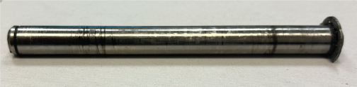
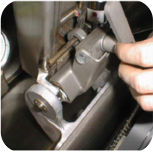
Use a hammer and punch to drive out the hinge pin. Visually inspect the hinge pin for any deformity. If the hinge pin shows any damage, it must be replaced when instructed to reinstall it.
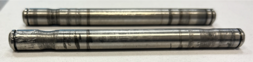
If you cannot drive out the hinge pin because it has a damaged end that appears mushroomed, use the Cut Off Wheel to cut and remove it.
Reference the images below to determine if the hinge pin is re-useable or needs to be replaced.
Re-usable
Damaged (needs replacement)
-
Remove the existing lid hinge spring and discard.
-
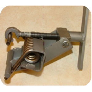
Place the replacement spring into Spring Loading Tool as shown.
-
Slip hook over the curved top portion of the spring.
-
Turn the tool handle clockwise to completely tighten the hook, using the reverse order of removing the spring.
-
Position the new spring into place under the crossarm.
-
Gently tap the lid hinge pin into place with hammer.
-
Clip Tru-Arc locks on each end of the lid hinge pin.
-
Turn the tool handle counterclockwise to loosen the hook and remove the tool.
-
Lubricate the new spring generously with Spindle Lube #12124 and replace the hinge cover.
-
Reinstall the lid.
After reinstalling the lid, it is recommended to perform the limit stop adjustment.
Two Tru-Arc locks are required for each lid hinge pin.
Related Content
Replacing the Lid Cover Assembly
Replacing the Lid Latch Spring
Replacing the Safety Relief Valve
Replacing the Deadweight Valve
Pressure Assist Features and Function
Replacing the Pressure Regulation and Exhaust Components
4 Head PFE 500/ PFG 600 Removing the Lid
Pressure Assist Kit Installation
Troubleshooting an W-1 Low Voltage Error Code
Direct connect oil system operating instructions
Electronic C2000 Simple Control Retrofit Kit
RLink programming instructions
PFE 500/PFG 600 Wi-Fi Verification and Troubleshooting Instructions
PFE 500/PFG 600 Hybrid Control Installation Instructions
2nd Generation Radio for SMS: Hardware Installation
2nd Generation Radio for SMS: Software Update
FM08-748 2nd Generation Radio for SMS: Troubleshooting
Instructions for Fryer Control Replacement Kits
SMS 20 Auto Polish Programming Instructions
Temperature Probe Gauge Instructions
CFA PFE 500 Hybrid Wi-Fi Status Check
Replacing Condensation Box Assembly
Replacing the Deadweight Valve
Pressure Assist Features and Function
Installation of PFG 600 and PFG 600 SSI FM07-366 Electromechanical to C1000 Retrofit
PFG 600 SSI Electronic C1000 to C8000 Retrofit Kit
Direct connect retrofit PFG 600
Direct connect retrofit PFG-600
PFG 600 Ignition Module Retrofit Kit
PFG 600 SSI Fryers Gas Valve Replacement Kit
SAE Thread Filter Pump Installation
Pre VA SAE Thread Filter Pump Installation
Hybrid Control and Wi-Fi Installation
Reference
PFE 500 and 561 Inspection and Planned Maintenance
PFE 500 KFC Annual Inspection Certification