Crossarm Repair Kit
9/16 in. Socket
3 in. Extension
Ratchet
Torque Wrench lbs/ft
3/32 in. Hex key
Putty Knife
Spring Tool
Kit number
182528
182529
182530
Estimated Time
1.5 to 2 hours
Lid Assembly Overview
The crossarm repair kit provides servicers with a complete and safe way to repair the entire center arm assembly.
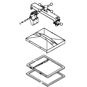
Replacement parts requiring spindle disassembly are no longer available. If any of the spindle parts require replacement on new or existing units, the crossarm assembly needs to be replaced with either of the options listed below.
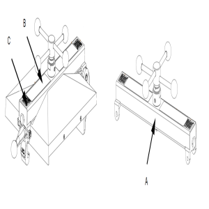
| Lid and Crossarm Assembly | Crossarm with Spindle Assembly Only |
|---|---|
|
|
|
- 182530-1XX UL w/language labels - 182530-2XX CE w/language labels |
- 182528-1XX UL w/language labels - 182528-2XX CE w/language labels |
|
This option comes with the complete crossarm assembly (i.e., spindle, rear hinge, front latch) and complete lid (i.e., pressure switch, gasket) ready for installation. |
This option provides the crossarm and spindle assembly only. The rear hinge assembly, and front latch assembly must be transferred from the old crossarm to the new crossarm. |

|
To avoid electrical shock or property damage, move the power switch to OFF and disconnect power. |
Separating Crossarm from Lid Assembly
-
Remove power form fryer.
-
Drain oil and allow fryer to cool before proceeding.
-
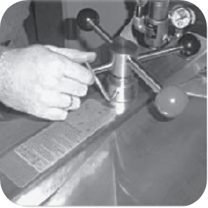
Close lid cover and turn spindle counterclockwise until it stops.
-
Pull the lid release pin on front of crossarm.
-
Lift the latch and raise the crossarm.
Removing Crossarm Assembly
-
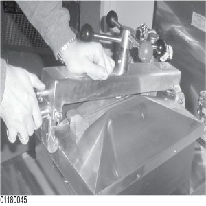
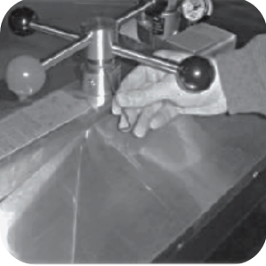
Use a ratchet with a 9/16 in. wocket and extension to remove the four bolts on the back of the crossarm holding it to the vat. Do not use a torque wrench as a breaker bar.
-
Scrub the mounting surface with degreaser and a putty knife until clean.
Replacing the Rear Hinge and Front Lid Latch
If using the 182528-XXX replacement crossarm only kit, the rear hinge and front latch from the broken crossarm must be transferred to the new crossarm. If the new crossarm has a hinge and latch, continue to Install the Crossarm.
Replacing Rear Hinge
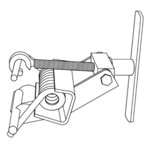
- Use the spring tool to remove torsional load form the existing rear spring.
- Use a flat edge screwdriver to remove the retaining ring from one end of the pin.
- Pull out the pin.
- Transfer the hinge to the new crossarm.
- Place the spring into position, and then install the pin through the spring.
- Install the retaining ring.
- Remove the spring tool.
Replacing Front Lid Latch
- Use a flat edge screwdriver to remove retaining ring from one end of the pin.
- Pull out the pin.
- Transfer the lid latch to the new crossarm.
- Install the retaining ring.
Installing the New Crossarm
This procedure may require two people. Thread sealant is not used.
- Place the crossarm mounting plate against the back of the vat. Ensure the holes are aligned.
- Use a ratchet with a 9/16 in. socket and extension to install four bolts with lock-washers and tighten to snug.
- With a 9/16 in. socket and 3 in. extension or a deep well socket, use a torque wrench to tighten each bolt to 40 lb-ft (54 Nm), use a star pattern.
Lubricating the Crossarm

- Use spindle lube to lubricate the threads of the spindle and the thrust ball.
- Lubricate the top of the ball seat and locking pin.
Reattaching Crossarm to the Lid
- Place the lid cover on the vat.
- Thread the spindle counterclockwise until it is completely extended.
- Align the rear retaining hook on lid cover in the center slot of the crossarm.
-
Push the crossarm down and pull out on lid release pin.
- Push the lid to rear of vat and latch the crossarm to the lid cover, and then release the pin.
- Check that lid cover is fastened properly before raising.
- Perform a lid limit stop adjustment.
Adjusting Limit Stop and Testing Lid Operation
To prevent damage, this procedure must be performed every 90-days and after a new gasket and / or lid replacement.
-
Loosen the hex-head set screws on the bottom of the collar of the limit stop assembly.
-
Turn the inner collar of the limit stop clockwise as far as possible. Find the small hole in the inner collar and use a small hex-head wrench or cross-tip head to help in turning the collar.
- Close the lid and turn the spindle until the lid gasket meets the top of the vat rim.
- From this position, turn the spindle at least 3/4 of a turn, but no more than one full turn.
- After rotating the spindle to this point, slightly extend the spindle past this position. The spindle should be at the seven o'clock position.
- If necessary, remove the knobs and change their position to align the redknob with the red knob on the lid cover lid latch. When in the normal operating position, both red knobs should be aligned.
- Adjust the limit stop by turning it counterclockwise until it stops against the bottom hub of the spindle.
- Tighten the hex-head set screw.
- Unit is now ready for use.
Related Content
Replacing the Lid Cover Assembly
Replacing the Lid Latch Spring
Replacing the Safety Relief Valve
Replacing the Deadweight Valve
Pressure Assist Features and Function
Replacing the Pressure Regulation and Exhaust Components
4 Head PFE 500/ PFG 600 Removing the Lid
Pressure Assist Kit Installation
Troubleshooting an W-1 Low Voltage Error Code
Direct connect oil system operating instructions
Electronic C2000 Simple Control Retrofit Kit
RLink programming instructions
PFE 500/PFG 600 Wi-Fi Verification and Troubleshooting Instructions
PFE 500/PFG 600 Hybrid Control Installation Instructions
2nd Generation Radio for SMS: Hardware Installation
2nd Generation Radio for SMS: Software Update
FM08-748 2nd Generation Radio for SMS: Troubleshooting
Instructions for Fryer Control Replacement Kits
SMS 20 Auto Polish Programming Instructions
Temperature Probe Gauge Instructions
CFA PFE 500 Hybrid Wi-Fi Status Check
Replacing Condensation Box Assembly
Replacing the Deadweight Valve
Pressure Assist Features and Function
Installation of PFG 600 and PFG 600 SSI FM07-366 Electromechanical to C1000 Retrofit
PFG 600 SSI Electronic C1000 to C8000 Retrofit Kit
Direct connect retrofit PFG 600
Direct connect retrofit PFG-600
PFG 600 Ignition Module Retrofit Kit
PFG 600 SSI Fryers Gas Valve Replacement Kit
SAE Thread Filter Pump Installation
Pre VA SAE Thread Filter Pump Installation
Hybrid Control and Wi-Fi Installation
Reference
PFE 500 and 561 Inspection and Planned Maintenance
PFE 500 KFC Annual Inspection Certification