Installing the Power Cord Anti-Rotation Bracket
Cross Tip Driver / Square Head Driver
Flat Blade Driver
Drill
Needle Nose or Channel Lock Pliers
Anti-Rotation Bracket
2 Screws
Kit number
Estimated Time
30 minutes

|
To avoid electrical shock or property damage, disconnect power before installing or servicing equipment.A qualified technician must perform the installation. |
|
|
Only perform this procedure when the unit is cool or severe burns may result. |
Preparing the Cabinet
Use this kit to re-locate the main power cord to the rear access point. This is recommended for a middle unit or if space constraints exist on the sides.
-
Turn the power switch off and then unplug from the power source.
-
Remove all accessories and trays from cabinet.
-
Skip to step 7 if the cabinet doesn't need moved, otherwise continue to step 4.
-
Disconnect cabinet from bottom mounting brackets.
-
Ensure cabinet is cool to the touch before moving.
-
Carefully remove cabinet from table and move to area for servicing.
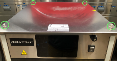
-
Using a cross-tip driver, remove the 4 screws holding the top shroud and remove.
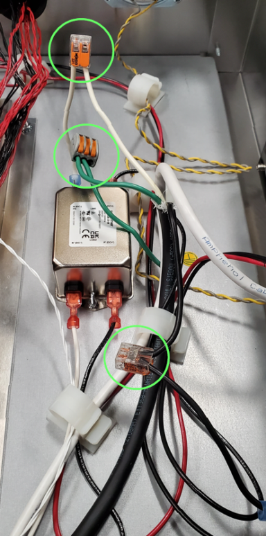
-
Locate the main power cord connections and disconnect. Note: Main power wires may have spade terminals and directly connected to components.
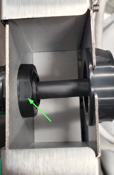
-
Using channel locks, carefully loosen the lock not on the back of the power cord strain relief and remove power cord assembly from unit.
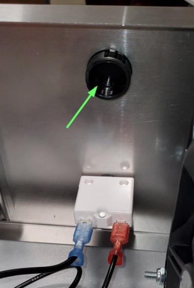
-
Locate the plug on the rear shroud of unit above the reset breaker and using a flat blade driver or needle nose pliers, remove the access plug from shroud.
-
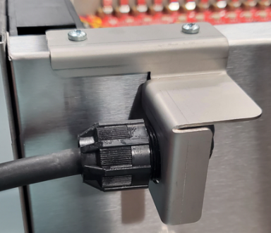
Install power cord assembly through rear access with strain relief pointing to the left and tighten to snug.
-
Mount the anti-rotation bracket to the unit using the two screws provided in kit making sure to mount bracket around power cord strain relief.
-
Fully tighten strain relief.
-
Working in reverse, complete steps 8 through 1 and return cabinet to operation.
Installing New Power Cord Assembly
Related Content
Troubleshooting the E-4A Cabinet Control Enclosure Overheating
Troubleshooting the E-4B Heat Sink Probe Overheated
Troubleshooting the E-5 Error Code Shelf Temperature Too Hot
Troubleshooting the E-6A Error Code Temp Probe Open
Troubleshooting the E-210 Cooling Fan Failure
Troubleshooting the E-216 Shelf temp too low
Replacing the UHC 600 Power Supply
Replacing the I/O Control Board
Reference