Replacing the Bulk Fill Selector Valve
7/8” wrench
crosshead screwdriver
Drill gun with crosshead bit
1/4 in. hex-key
3/8 in. socket
Adjustable wrench
9/16 in. hex-key
13/16” wrench
1/4” wrench
Thread sealant
Kit number

|
To avoid electrical shock or property damage, move the power switch to OFF and disconnect power. |
Setting Up Bulk Fill
-
Using a crosshead screwdriver, remove screws from right side panel.
-
Using a crosshead screwdriver, remove the lower rear shroud and set aside.
-
Standing at the rear of the unit, the first vat to the right is vat #1 then moving to the left are vats 2, 3, etc.
-
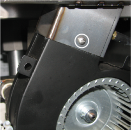
Using a crosshead screwdriver or an electric drill with a crosshead tip, remove the three screws securing the blower to the flues. Set the blowers aside. Both blowers on an EEG-242 will need removed to proceed with installation. All other units will need the two blowers on the appropriate vats removed.
-
Using a 7/8” wrench, remove flex lines from selector valve.
-
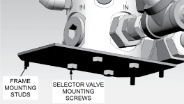
Using a 3/8 nut driver or socket, remove four mounting nuts holding selector valve mounting plate to frame member.
-
Remove four mounting screws holding mounting plate to Selector Valve Using a 7/16 wrench.
-
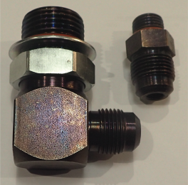
Locate the #12 SAE elbow and the #6 SAE Straight included in the kit.
-
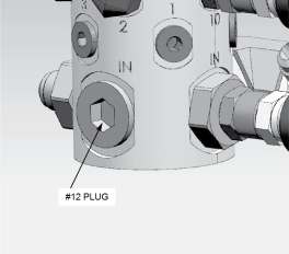
Using a 9/16 ” hex driver, remove the plug at port #12 facing towards the back of the fryer.
-
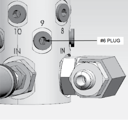
Using a 1/4 ” hex driver, remove #6 plug in Port #9 towards the right-hand side of the fryer.
-
Using a 1 1/4” wrench, install the #12 SAE 90° Elbow with 90° Flare fitting on one end into the Selector Valve opening.
-
Using a 13/16” wrench, attach the #6 SAE straight fitting in to the #9 Port.
-
Reattach Selector Valve mounting plate back to Selector Valve using existing hardware. New elbow should be Parallel to mounting plate.
-
Mount Selector Valve back to frame using existing hardware and reattach all flexible lines.
-
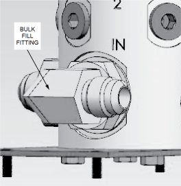
If the unit was not set up with bulk oil fill, remove the rectangular cover plate from the lower rail of the fryer. Keep the original mounting nuts for reuse on the new mounting plate.
-
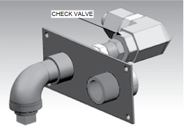
Attach the new Bulk Fill/Dispose plate supplied in the kit. Inspect the check valve to confirm the arrow is pointing away from the mounting plate.
-
Connect a 7” Flexible Line included in kit from #12 SAE Elbow new fitting to rear mounting plate for a 2 vat or a 21” Flexible Line for a 3 & 4 vat.
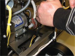
Modifying the JIB Inlet
-
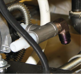
Using an adjustable wrench, remove the existing fitting in the JIB pump.
-
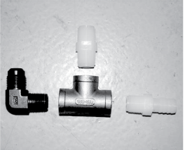
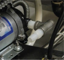
Locate the elbow fitting, tee fitting, plastic barbed fitting, plastic nipple.
-
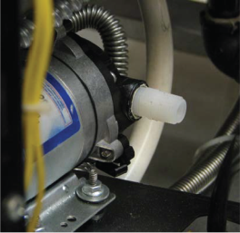
Install the plastic nipple into the JIB pump.
-
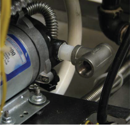
Install the T-fitting onto the plastic nipple so that the open ends are facing either side of the unit.
-
Install the plastic barb-fitting into the T-fitting nearest the JIB pump body.
-
Install the elbow fitting to the T-fitting on the opposite side of the barb fitting.
-
Reconnect the JIB pick up tube to the plastic fitting on the back of the JIB pump.
-
Clamp the hose in place.
-
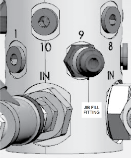
Locate the JIB box fill flex line (24” long). Connect to the Selector Valve JIB fill fitting and to the new fitting on the JIB pump.
-
After flex lines are tightened, use the provided zip ties to secure the flex lines in place.
-
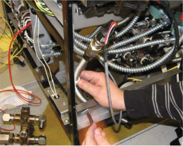
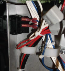
Using a crosshead screwdriver, remove the clamp securing the transducer to the frame. Move transducer out of the way.
-
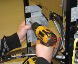
Locate the bulk supply connection box in the kit. Place the mounting tabs of the box on the vertical and horizontal frame section. Secure the box in place with four self-tapping screws.
-
Place transducer and clip back in the same area as removed.
-
Secure clip and transducer to the stud on the wiring box.
For CE Units
-
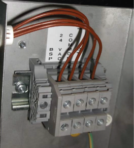
Mount the terminal block onto the fryer on the open studs located inside the terminal block box. The mount should be above the terminal block power cord.
-
Apply the label above or below the terminal block to denote the appropriate location of the wiring.
Wire Bulk Oil Supply Connection
-
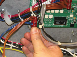
Locate the wiring harness included with the brown and blue wires.
-
Plug the 12-pin connector into the AIF board.
-
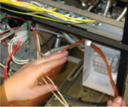
Route the four brown wires to the back of the fryer through the big, black bushing to the bulk supply box through the small white bushing.
-
Match the labeled wires to the correct location in the connection box.
Install Toggle Switch
-
Remove plate on the upper front of the AIF box.
-
Insert switch onto the AIF box opening.
-
Connect the wires from the 12-pin connector to the switch.
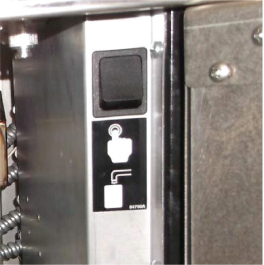
-
Apply the provided label to the AIF box to indicate the JIB fill feature.
Set up Controls for Bulk Oil Fill
-
Press the (P) button for 5 seconds until “SP PROG” and “ENTER CODE” displays.
-
Enter code 1, 2, 3 and “SP-1 TEMP FORMAT” will flash on the display.
-
Press the right or left arrow keys to “SP-22”. Change Bulk Oil Supply to “YES”.
-
Exit Special Program.
-
Repeat these steps as needed for remaining controls.
Bulk Oil Connection Instructions have been provided with this kit. Please leave in location where they can be located for the bulk supply company to reference when connecting to the fryer.
Related Content
Replacing the Selector Valve Motor Encoder
Replacing the Flange Mount Filter Pump and Motor
Replacing the Hubmounted Filter Pump and Motor
Adjusting the Drain Valve Actuator
Troubleshooting Oil Not Pumping
Troubleshooting the Check Pan Message on Evolution Elite Fryers
Replacing the EEG Fryer Generation 4 Selector Valve Motor
Troubleshooting EEG 16X and 24X E-15 Drain Open Error Code
Troubleshooting EEG 16X and 24X E-18 Level Probe Failure Error Code
Troubleshooting EEG 16X and 24X Oil Not Pumping Error Code
EEG E 82D Error Code Troubleshooting
Smart Touch Software Installation Instructions
Reference