Applies to:
![]()
MAP Theory of Operation
Purpose
The F5 Modular Architecture Platform (MAP) system allows for control of printed circuit boards (PCBs) responsible for each of the fryer's sub-systems. MAP allows the fryer sub-systems to integrate for more effective operation and communication. The MAP system is connected electrically by a Power Distribution PCB which converts incoming line AC voltage to 24 volts DC that is required by each component. Communication between the MAP system components is handled via CAN bus messaging. The F5 MAP system consists of:
-
Power Distribution PCB
-
Control Panel (VDM/HMI)
-
Power Modulation Unit (PMU) - Electric Heat
-
Gas Modulation Unit (GMU) - Gas Heat
-
Oil Management System (OMS)
CAN Bus
The F5 MAP system is a Controller Area Network (CAN) serial communication bus of components which operate all fryer sub-systems. CAN communication is designed for robust and flexible performance in harsh environments. Each component in the CAN bus system is linked together by a chain of communication cables. The CAN communication will remain intact should a failure of one of the PCBs occur as long as the physical electrical traces are present. CAN communication would fail if one of the cables become disconnected or are severed.
Addressing
Within the MAP system, addressing is used to properly identify the type and location of components so that a CAN message reaches its intended destination. If the address of a component does not match the stored configuration value then an error will occur.
Addressing of vat/heat type and PMUs/GMUs are handled by a series magnets physically mounted to the fryer and Hall effect sensors that are built into the component. The address for vat/heat type and PMU location is a string of binary digits 0 or 1, determined by the quantity and location of magnets mounted on the midshelf PMU board shroud.
NOTE - Vats 1 thru 4 have different PMU board shrouds. The magnets are all the same. Quantity and location of magnets determine the configuration value.
-
Vat/Heat Type Address (2 digits)
Magnet Configuration Vat Type Heat Type Vat Type (U13) Heat Type (U11) Open Electric 0 0 Open Gas 0 1 Flex Electric 1 0 Flex Gas 1 1 0 = Magnet not present, Hall effect sensor open
1 = Magnet present, Hall effect sensor closed
-
PMU/GMU Location Address (3 digits)
| Well 1 | Well 2 | Well 3 | Well 4 | |||||
|---|---|---|---|---|---|---|---|---|
| Control 1 - Address 1 | Control 2 - Address 2 | Control 3 - Address 3 | Control 4 - Address 4 | |||||
| Vat 1 | Vat 2 | Vat 3 | Vat 4 | Vat 5 | Vat 6 | Vat 7 | Vat 8 | |
| Left Split Vat ONLY | Right Split Vat OR Full Vat | Left Split Vat ONLY | Right Split Vat OR Full Vat | Left Split Vat ONLY | Right Split Vat OR Full Vat | Left Split Vat ONLY | Right Split Vat OR Full Vat | |
| PMU/GMU |
PMU 1 GMU 1 |
PMU 2 GMU 2 |
PMU 3 GMU 3 |
PMU 4 GMU 4 |
PMU 5 GMU 5 |
PMU 6 GMU 6 |
PMU 7 GMU 7 |
PMU 8 GMU 8 |
| Magnet Config. | Address 000 | Address 001 | Address 010 | Address 011 | Address 100 | Address 101 | Address 110 | Address 111 |
| U31 | 0 | 0 | 0 | 0 | 1 | 1 | 1 | 1 |
| U30 | 0 | 0 | 1 | 1 | 0 | 0 | 1 | 1 |
| U29 | 0 | 1 | 0 | 1 | 0 | 1 | 0 | 1 |
0 = Magnet not present, Hall effect sensor open
1 = Magnet present, Hall effect sensor closed
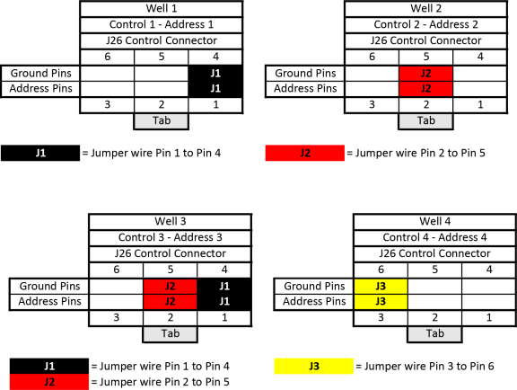
Each control panel also has a location address that is created by a unique configuration of jumper wires on a tethered addressing cable connector. Control panels are numbered 1 through 4 from left to right as viewed from the fryer's front.
Control Location Address:

NOTE - Swapping of components in the MAP system is not an effective method to troubleshoot or isolate problems, and will likely lead to system errors.
NOTE - J26 Connector as viewed with control panel lowered.
Related Content
ATO System Sequence of Operation
ATO System Theory of Operation
Bulk Oil System Sequence of Operation
Bulk Oil System Theory of Operation
Cart Dispose System Sequence of Operation
Cart Dispose System Theory of Operation
Control MAP Sequence of Operation
Control MAP Theory of Operation
Electric Heat Sequence of Operation
Electric Heat Theory of Operation
Filtering Sequence of Operation
PMU Hi Limit Theory of Operation
Reference
LVE 300 Software (without Connectivity)