Applies to:
![]()
PMU Hi Limit Theory of Operation
PMU Purpose
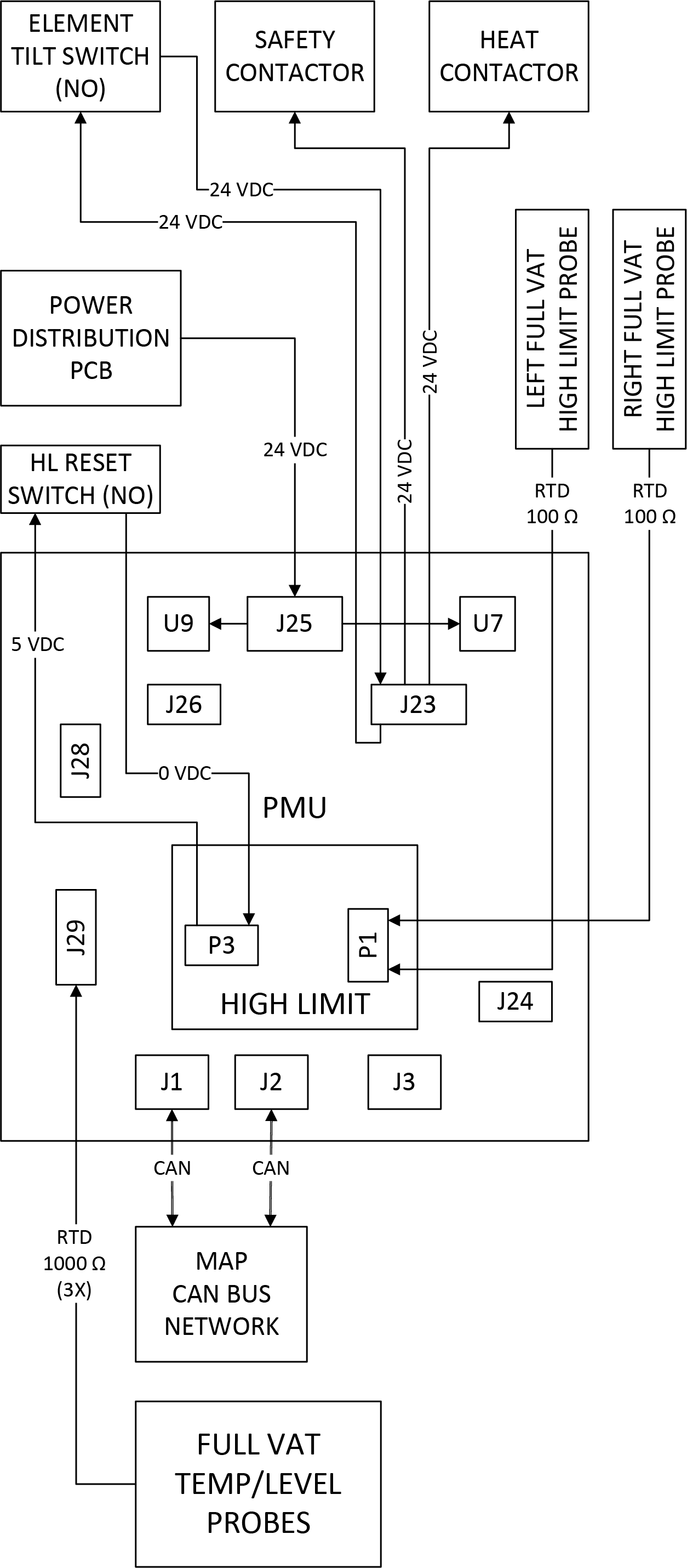
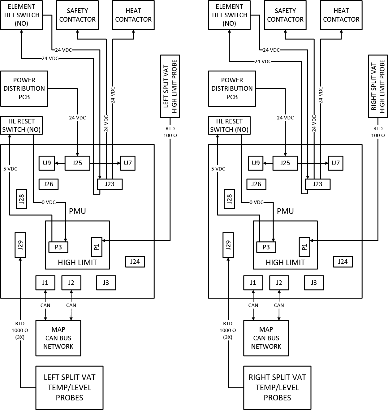
Control of the electric heat system for each vat is handled by a PMU that is powered by 24 volts DC from the Power Distribution PCB. Incoming to the PMU are main and level resistance temperature detector (RTD) probe resistances for the respective vat. The RTD probes provide oil temperature and level detection feedback to the control system. Each main and level RTD probe has a baseline of 1000 ohms at 32°F (0°C) with increased resistance as oil temperature rises. Safety circuits for the High Limit PCB and element tilt switch are connected to the PMU and must be closed before heat is applied. Outputs of the PMU are 24 volts DC to the safety and heat contactor coils along with the High Limit PCB. Two PMU e-fuses are built-in to prevent excess current draw situations.
-
One PMU per vat, full or split
-
PMU locations 1 through 8 with specific 3 digit address
-
Odd numbered locations: Left split vat only
-
Even numbered locations: Full vat or right split vat
-
-
Analysis of main and level probes resistance input from the respective vat
-
1000 ohm RTD probes for oil temperature and level detection feedback
-
Safety circuits for High Limit PCB and element tilt switch
-
24 volts DC output to safety and heat contactor coils
-
LEDs to indicate statuses
-
Two e-fuses for excess current draw
-
Connected to CAN bus operations network
High Limit PCB Purpose
Monitoring of each vat's high limit safety circuit is handled by the High Limit PCB. Power for the high limit PCB is supplied by 24 volts DC from the Power Distribution PCB through its connection to the PMU. Input to the High Limit PCB is provided by one or two resistance temperature detector (RTD) probes. The RTD probes are mounted to sense and provide element temperature feedback to the control system. Each high limit RTD probe has a baseline of 100 ohms at 32°F (0°C) with increased resistance as element temperature rises. Should the element temperature reach the high limit set point, the safety circuit is then opened and heating of that vat is no longer allowed. Heating of the vat will be allowed once the element temperature is below the reset point, and reset switch pressed by the operator. Output of the High Limit PCB is 5 volts DC to the normally open (NO) reset switch. When the reset switch is pressed and momentarily closed, 5 volts DC returns to the High Limit PCB providing the reset signal.
-
One High Limit PCB per vat, full or split
-
Mounted directly to respective PMU
-
100 ohm RTD probe(s) for element temperature feedback
-
Full vat has two RTD probes mounted to element
-
P1 connector has no jumper wire to identify as a full vat
-
-
Split vat has one RTD probe mounted per element
-
P1 connector has J1 jumper wire to identify as a split vat
-
J2 jumper wire in place of second RTD probe used on full vat only
-
-
High limit safety circuit opens when element set point temperature is reached
-
5 volts DC output signal when normally open reset switch is momentarily closed
-
LEDs to indicate statuses
-
Solid red LED indicates high limit open or stuck reset condition.
-
Solid yellow LED indicates high limit closed and 24 volts DC present.
-
Flashing red LED indicates a critical error and a power cycle to the PMU/High Limit is required.
-
Related Content
ATO System Sequence of Operation
ATO System Theory of Operation
Bulk Oil System Sequence of Operation
Bulk Oil System Theory of Operation
Cart Dispose System Sequence of Operation
Cart Dispose System Theory of Operation
Control MAP Sequence of Operation
Control MAP Theory of Operation
Electric Heat Sequence of Operation
Electric Heat Theory of Operation
Filtering Sequence of Operation
Reference