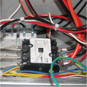
Replacing the Primary Contactor

|
To avoid electrical shock or property damage, move the power switch to OFF and disconnect power. |
Do not connect L1 & L2 to a circuit operating at more than 150 volts to ground (gnd) or component damage may result.
-
Lower the control board.
-
Mark the location of the wires.
-
Use a crosshead screwdriver to remove the:
-
L1, L2, and L3 wires from the contactor.
-
T1, T2, and T3 wires from the side of the contactor.
-
RS1 and RS2 yellow wires.
-
-
Use a 3/8 inch nut-driver to remove the nuts that secure the contactor to the shroud.
-
Lift up on the contactor and remove it from the studs.
-
Place the new contactor on to the studs, and then use a 3/8 in. nut-driver to secure in place.
-
Use a crosshead screwdriver to install the:
-
RS1 and RS2 yellow wires.
-
T1, T2, and T3 wires to the side of the contactor.
-
L1, L2, and L3 wires to the contactor.
-
-
Install the control board.
Related Content
Replacing the AIF Multi-Tab Transformer
Replacing the Control Transformer
Troubleshooting the Zigbee Radio
ZigBee Radio Communication Kit
Menu Card Removal Replacement Instructions
Save and Load Setpoint Instructions
PXE 100 Troubleshooting the E-41 Programming Settings Lost Error Code
Reference
Product Racking Recommendations
PXE 100 Inspection and Planned Maintenance