Troubleshooting the Zigbee Radio
In order for seamless communication between the fryer’s control board and the operator’s data tracking system the following steps are required:
-
The Digi radio must have uninterrupted power from the fryer’s control board.
-
The fryer’s control board must be able to communicate (pass data) bidirectionally with the Digi Radio over the wired connection.
-
The Digi radio must be able to convert data into the ZigBee network protocol.
-
The Digi radio must be able to transmit wireless data using the ZigBee protocol.
-
The Digi radio must be seen on the operator’s network.
-
The Digi radio must be able to Join the operator’s OPS/QPM environment, which is KFC specific.
Each of these steps can be a failure point.
Digi ZigBee Radio Basics
Network Connectivity
Just because a Digi ZigBee radio module can hear transmissions from a ZigBee network, it does not mean the radio module is part of that network. In fact, any particular module may be able to hear transmissions from multiple ZigBee networks— just as your laptop may hear transmissions from multiple wireless networks—though it can connect to only one at a time, or might not be connected to any. When our controls and radio modules leave Henny Penny, they are sent out in an Unjoined state, which means they are not a member of any particular network group. Joining a radio is the process of having it locate and join a particular ZigBee network.
Joining a Network
The radio must be manually invited by the OPS/QPM computer to join the store’s ZigBee network. The OPS/QPM computer screen lists all the nearby radio modules that the network can communicate with and the operator selects a module and invites it to join the network.
There are options available in the ZigBee protocol to support an "auto-join" feature, but KFC is currently manually joining new radios at this time.
Once joined to the network, the radio automatically reconnects to that same network at each power up. Even if a fryer is unplugged and powered down for days, the radio module remembers the network that it has been assigned to, and automatically reconnects to it again the next time the fryer is plugged in.
Data Communication
The Digi radio can be powered on but not communicating. The radio needs to communicate with both the fryer’s software (control board) and the operator’s virtual network in order to seamlessly pass data. As an example, the data can flow successfully between the fryer and the Digi radio but never make it on to the operator’s virtual network, which inhibits the fryer’s data from reaching the operator’s Smart Kitchen software. Conversely the data may never make it from the fryer to the Digi radio because the radio was improperly installed, damaged, setting changes, fryer moved to a new location, or due to software or hardware failures. Ensure seamless data communication by doing the following:
Verifying Power
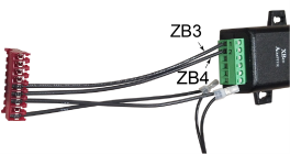
The Digi radio operates on 12 VDC. A power cable is provided in the kit. The barrel end of the wire is notched and plugs directly in to the Digi Radio. The other end is connected to a 9-pin connector and connects in to the back of a control board, to receive power.
Ensure the unit has power by doing the following:
-
Verify the Power light, that is adjacent to the barrel connector on the Digi Radio, is illuminated. If yes, continue to Communication Cables. If no, continue to step 2.
-
Verify the 9-pin connector is connected correctly, and not reversed. If correctly wired, continue to step 3. If incorrectly wired, repair and verify if the Digi Radio has power.
-
Use a volt meter to verify the control board’s 9-pin connector is providing 12 VDC of power. The barrel connector sleeve (ring) is negative, and the tip (interior) is positive. If yes, order a new Digi Radio and/or power cable. If no, diagnose and repair the control board’s power source (transformer).
Communication Cables
Two communication wires connect between the Digi radio’s terminal block and a 9-pin connector, the same 9-pin connector that the power wires connect to for a power source. These two wires provide the signals for half duplex communication between the Digi radio and the fryer’s control board. Ensure seamless data communication between the Digi radio and control board by doing the following:
-
Verify the 9-pin connector is connected correctly, and not reversed. If correctly wired, continue tostep 2. If incorrectly wired, repair and verify seamless data communication.
-
If the Digi radio hardware is installed and operating correctly, verify the fryer’s control board (software) is communicating with the Digi radio.
If SP-4 OPS/QPM Enabled is set to YES the control board monitors the RS-485 data link for messages from a ZigBee radio module and responds appropriately when requests are received.
If SP-4 OPS/QPM Enabled is set to NOthe control board does not attempt to communicate with the radio module (via RS-485). All ZigBee related information (displays) indicates OPS/QPM is -OFF- Set OPS/QPM Enabled to YES and then continue to step 3.
-
Complete the steps in section Verify Communication of Installing the Zigbee Radio and ensure the fryer’s Digi radio is Joined to the OPS/QPM network. Continue diagnostic steps as necessary by referring to ZigBee Radio Info Display.
ZigBee Radio Info Display
Use the information obtained from the ZigBee radio information display to further diagnose technical issues.
Access Info Display by doing the following:
-
Press the Menu and Info buttons together at the same time. Release the buttons once == INFO MODE == displays.
-
Press the left-arrow button once. The OPS/QPM RADIO screen displays.
Info Mode can not be used to enable or disable the OPS/QPM system. It simply provides access to the ZigBee Radio Info Display if the OPS/QPM system has already been enabled. The same information is available in Data Comm program mode, as item DC-2.
JOIN Screen
ZigBee: The check mark next to the ZigBee text in the middle display indicates that the module is actively receiving good messages from the radio module over the RS485 wired connection to the control. The check mark indicates that the radio module and fryer’s control board are communicating with each other. It does not indicate the radio is talking to the in-store wireless network. If the radio status displays a:
✓: Control has received a good message within the past 15 seconds.
- : Last good message was more than 15 seconds but less than 60 seconds ago.
X: Control has not received a good message in more than 60 seconds.
JOIN: The number displays join status reported by the radio module to the control.
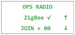
-
00 means the radio is currently joined to a network.
-
21, 23, or FF are typically shown for a radio module that is currently not joined to any network.
-
Other, transient values may appear when the radio has just powered up or is in the process of joining or unjoining a network.
CHANNEL Screen
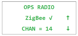
Displays the radio channel currently being used by the radio and network. If the radio is not currently joined to any network, 00 is typically displayed.
PAN ID Screen
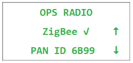
Displays the PAN ID number (Personal Area Network ID) of the ZigBee network the radio is currently joined to. If the radio is not currently joined to any network, FFFF is typically displayed.
RADIO SHORT ID Screen
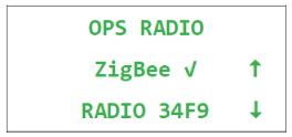
Displays the Short ID of the radio module, as it is currently addressed on the network. The number is dynamic and is assigned by the Operator’s network coordinator device when the radio module joins the network. The number is not necessarily tied to any static property, MAC address, or serial number of the radio itself. If the radio is unjoined from the network, then rejoined to the same network, it might end up with a different Short ID number. If the radio is not currently joined to any network, FFFE is typically displayed.
Reset / Unjoin Command
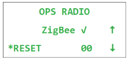
This option resets the radio module; Or rather, asks the radio module to reset itself. The radio module unjoins the network.
The number to the right of the RESET field displays the pending reset command. 00 means no reset is in progress. 01 means the process of resetting the radio module has been initiated, but the radio module has not received the message to reset itself yet.
To perform the reset operation, the user must press the button to the left of RESET. While holding the RESET button, the control beeps loudly and displays a countdown: 3,2,1... If the user continues holding the button until the countdown expires, the reset code is changed from 00 to 01, indicating a reset operation is in process. After the radio unjoins the network, 00 displays.
If the radio is already unjoined from the network, it might not respond to this command. In this case, the 01 status may display until the next time the control is turned off and back on again, which returns the control’s reset code to 00.
Modbus Packet Statistics
Displays statistics about the data packets received from the radio module (i.e. the wired RS-485/Modbus communications link between the ZigBee radio module and the control). These packets do not have any relationship to the wireless side of things and do not indicate anything about whether the radio is sending or receiving ZigBee wireless data.
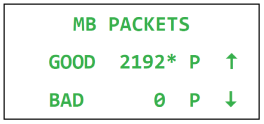
While on this display, the control chirps each time a good packet is received. A joined radio normally communicates with the control about every five seconds. The control sends a reply to the radio after each valid packet, and the radio normally sends several packets at each exchange. An unjoined radio module sends fewer packets and less frequently.
Each Modbus data packet must follow a certain format and must have a valid checksum byte, which confirms the integrity of the packet. If the checksum value is invalid, or if there is an interruption in the middle of the transmission, etc., the packet is discarded and the bad packet count is incremented.
Modbus Character RX/TX Statistics
Displays counts of the number of bytes received by the control from the radio module (RX), and the number of bytes transmitted by the control to the radio module (TX). These are characters on the wired RS-485 link between the radio module and the control. They do not reflect anything about the wireless side of things.
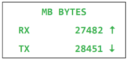
In our particular RS485 implementation, the control hears its own transmissions, so it can confirm that what it sent was transmitted correctly. The RX count reflects only the characters received from other devices (i.e. from the radio module). It does not include the characters the control sent.
Related Content
Replacing the Primary Contactor
Replacing the AIF Multi-Tab Transformer
Replacing the Control Transformer
ZigBee Radio Communication Kit
Menu Card Removal Replacement Instructions
Save and Load Setpoint Instructions
PXE 100 Troubleshooting the E-41 Programming Settings Lost Error Code
Reference
Product Racking Recommendations
PXE 100 Inspection and Planned Maintenance