PFE 580 and 582 Wiring Diagrams
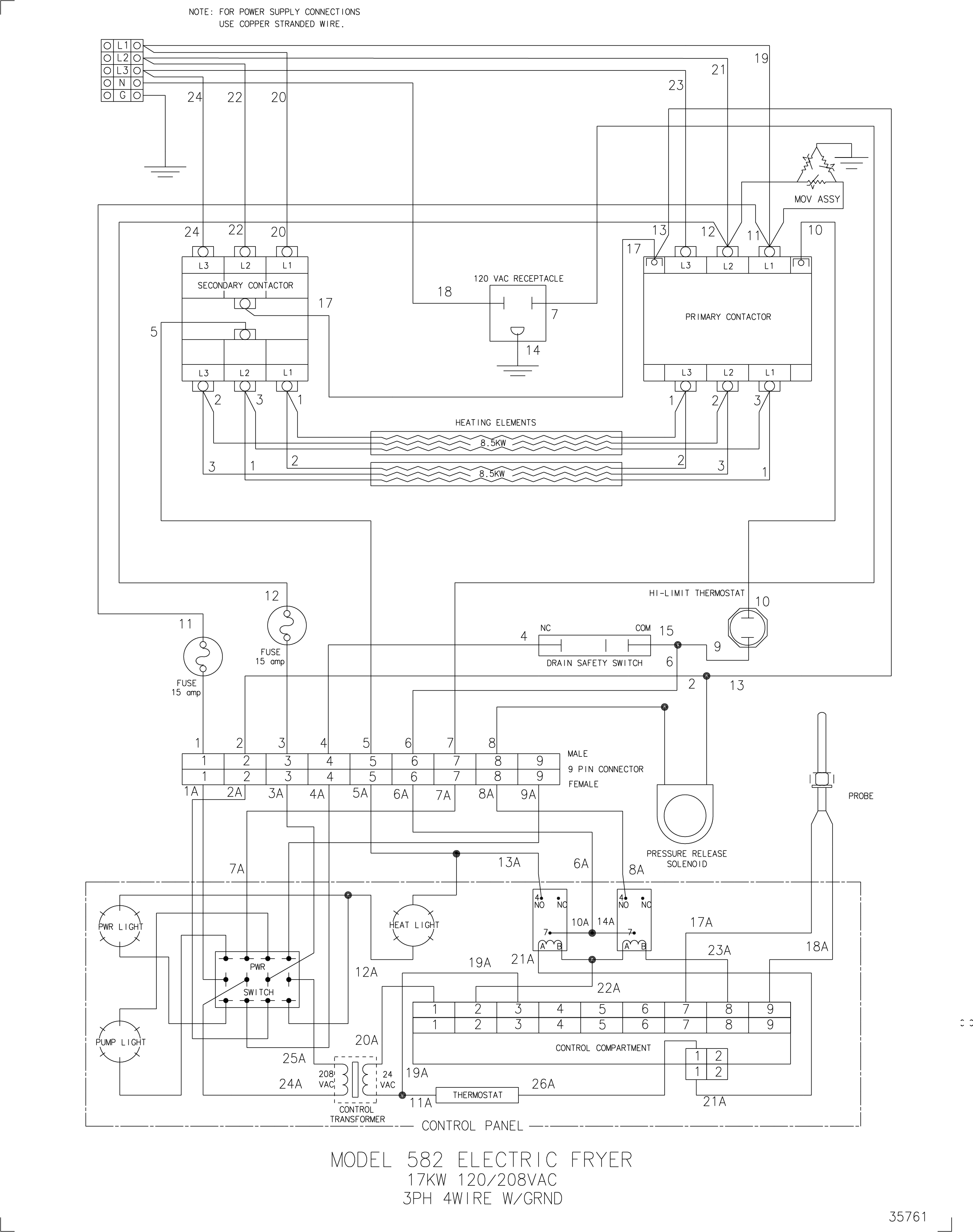
PFE 582 120V-208VAC, 17kw, 3 phase, 4W+G Wiring Diagram
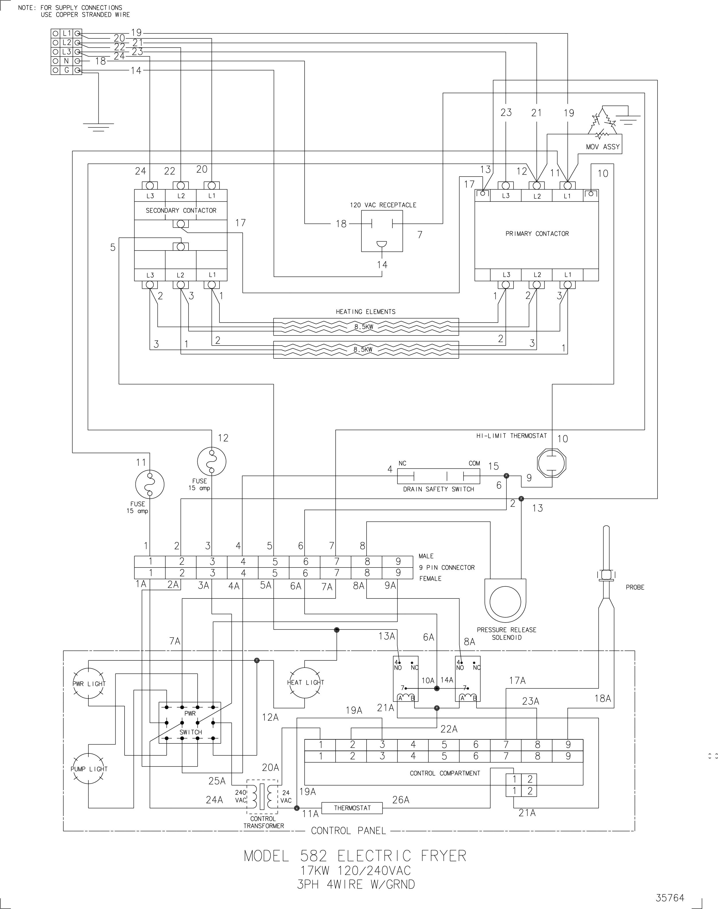
PFE 582 120V/240VAC, 17kw, 3 phase, 4W +G Wiring Diagram
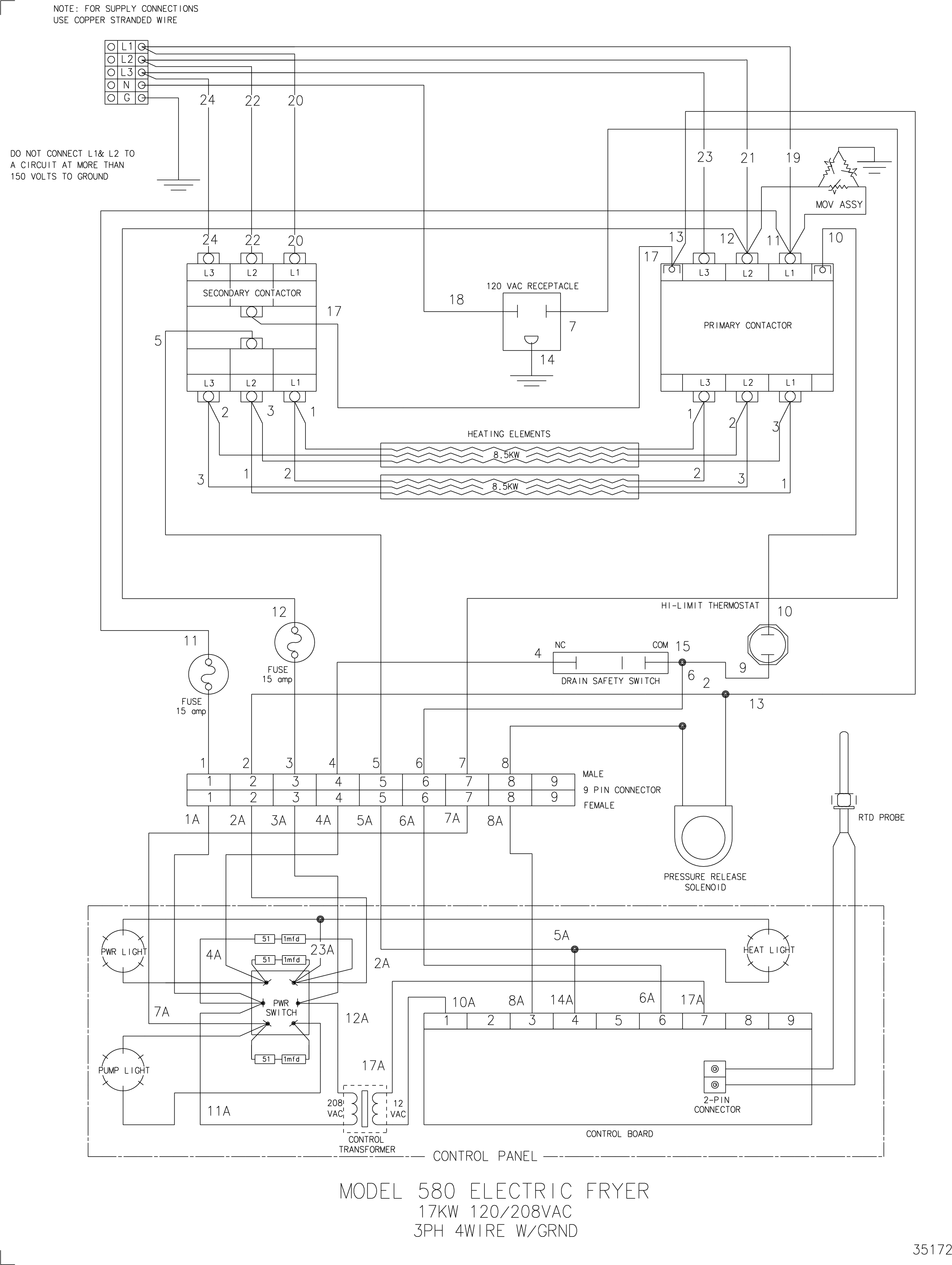
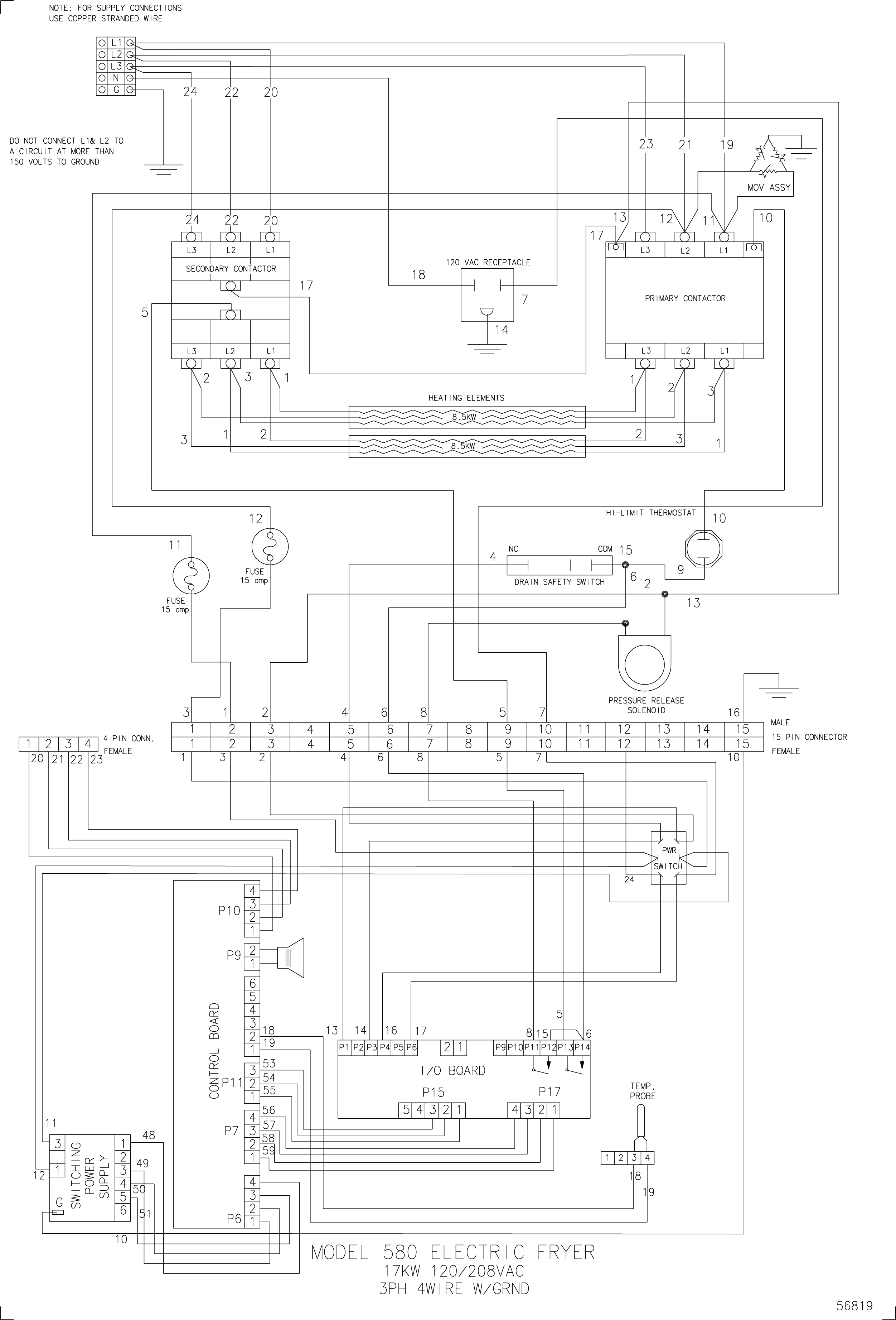
PFE 580 120/208VAC, 17kw, 3 phase, 4W +G Wiring Diagram
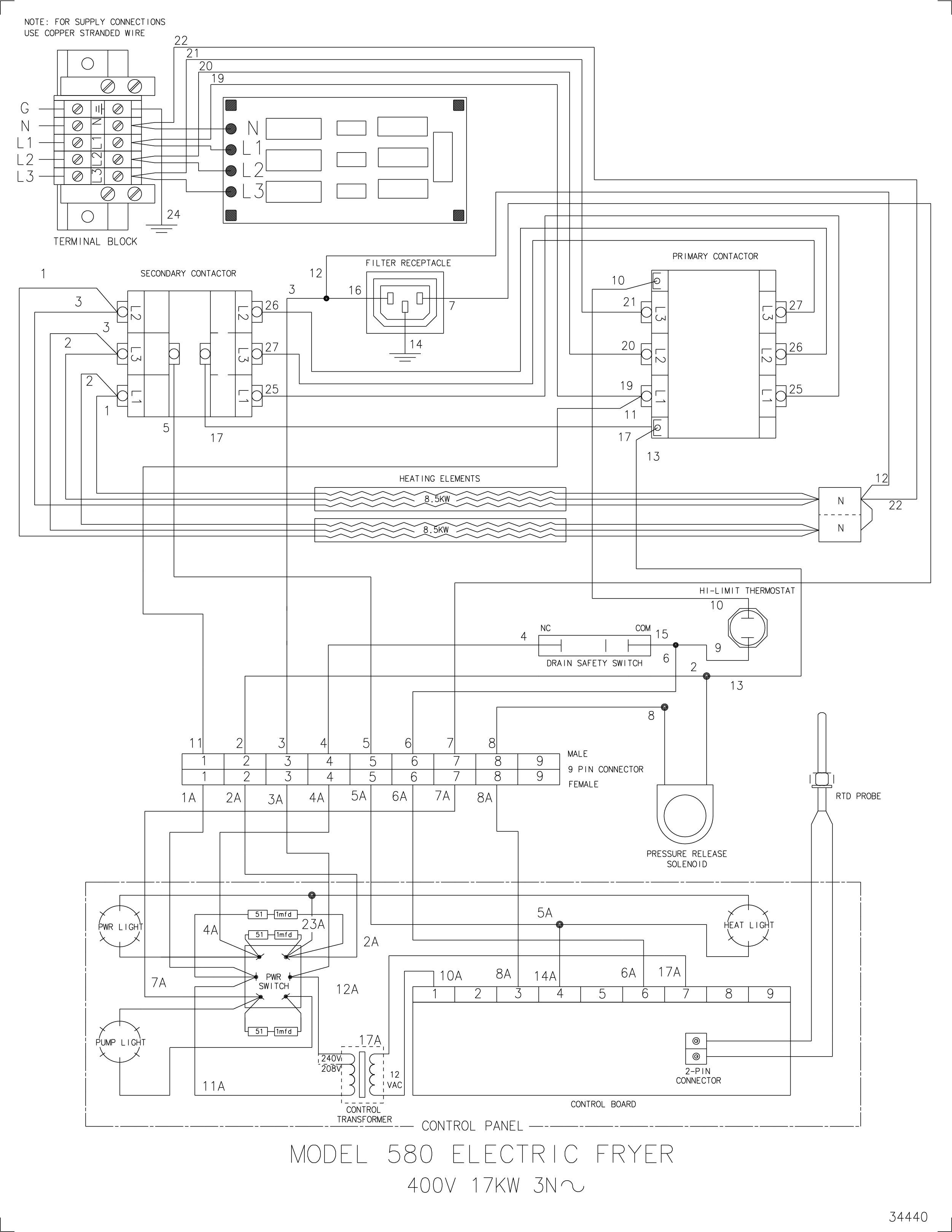
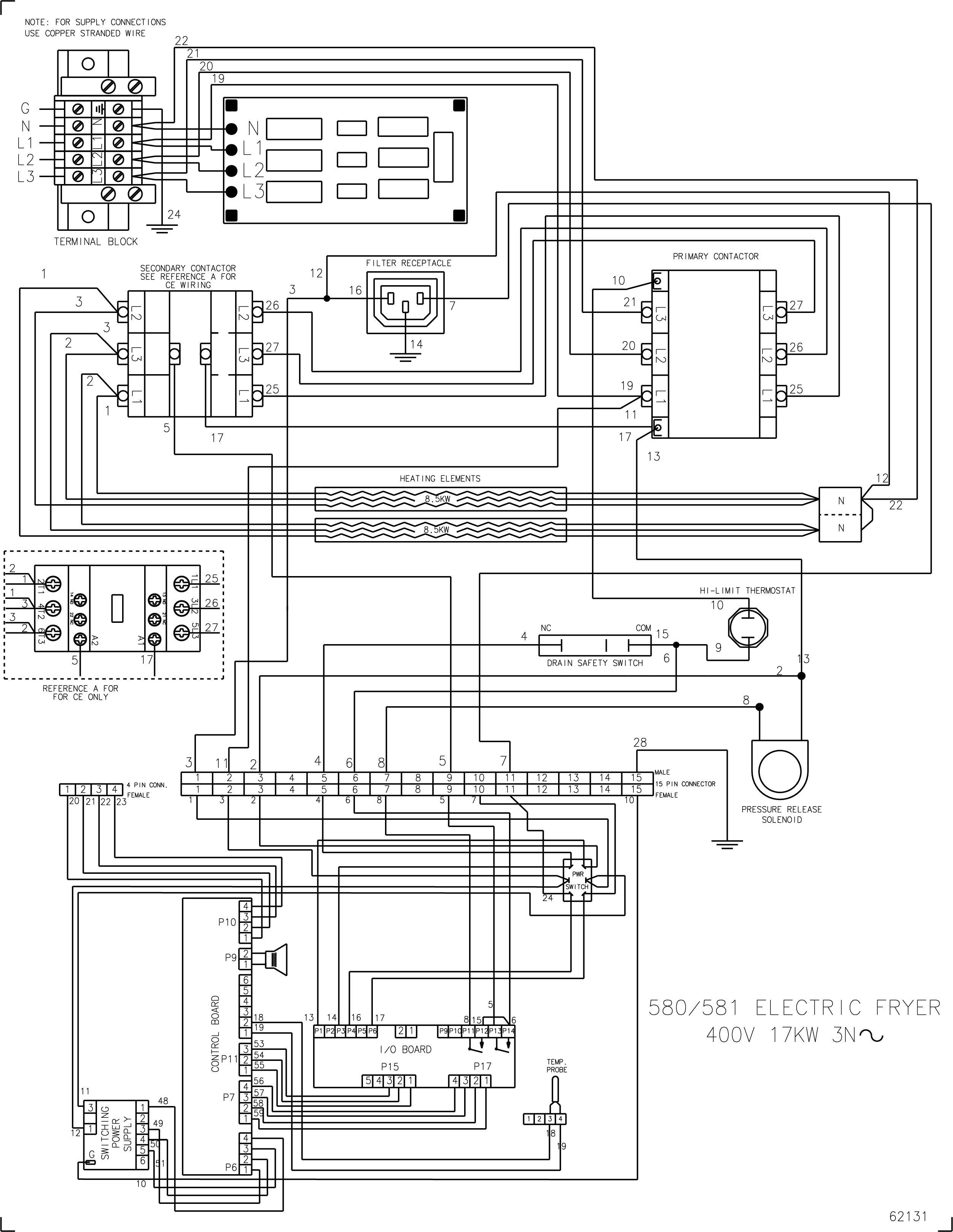
PFE 580 400VAC, 17kw, 3W +G Wiring Diagram
PFE 580 120/208VAC, 17kw, 3 phase, 4W +G Wiring Diagram
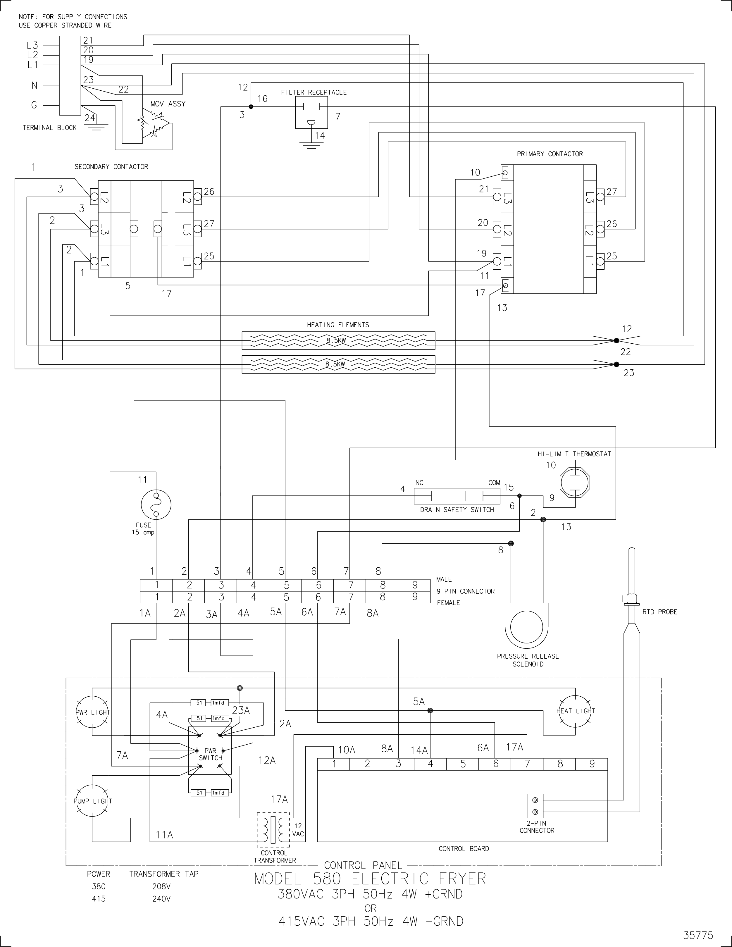
PFE 580 380-415VAC, 50Hz, 3 phase, 4W+G Wiring Diagram
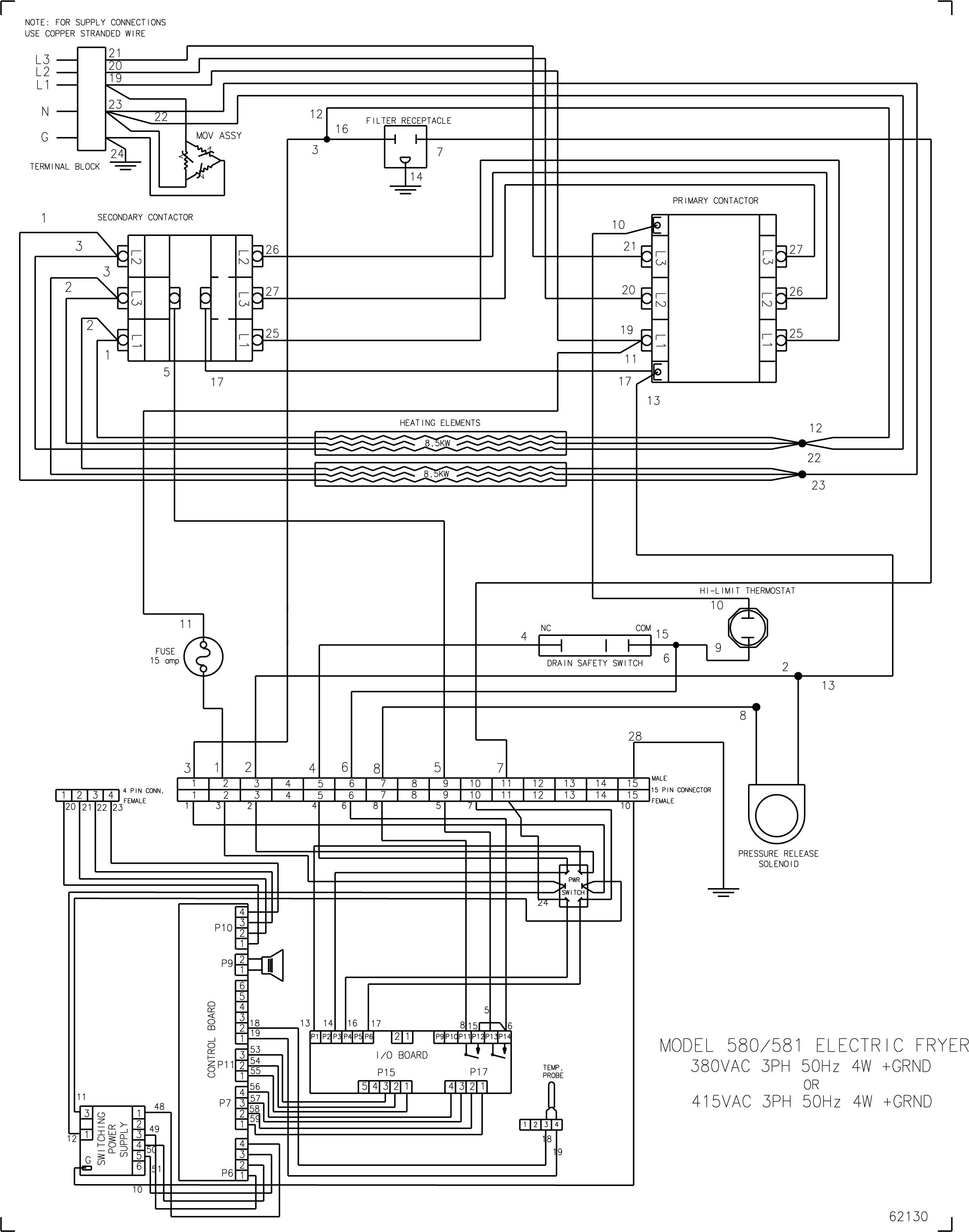
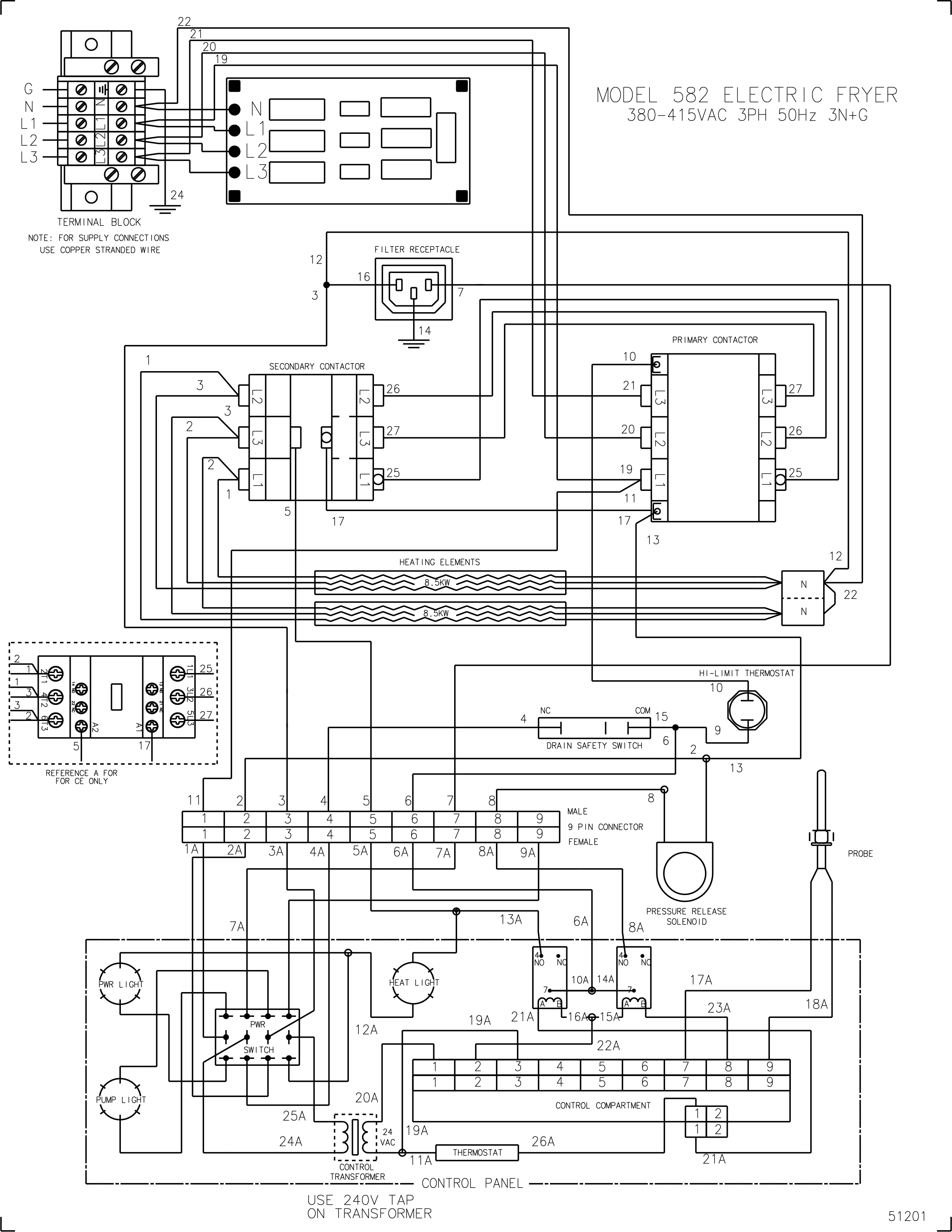
PFE 580 and 581 380-415VAC, 50Hz, 3 phase, 4W+G Wiring Diagram
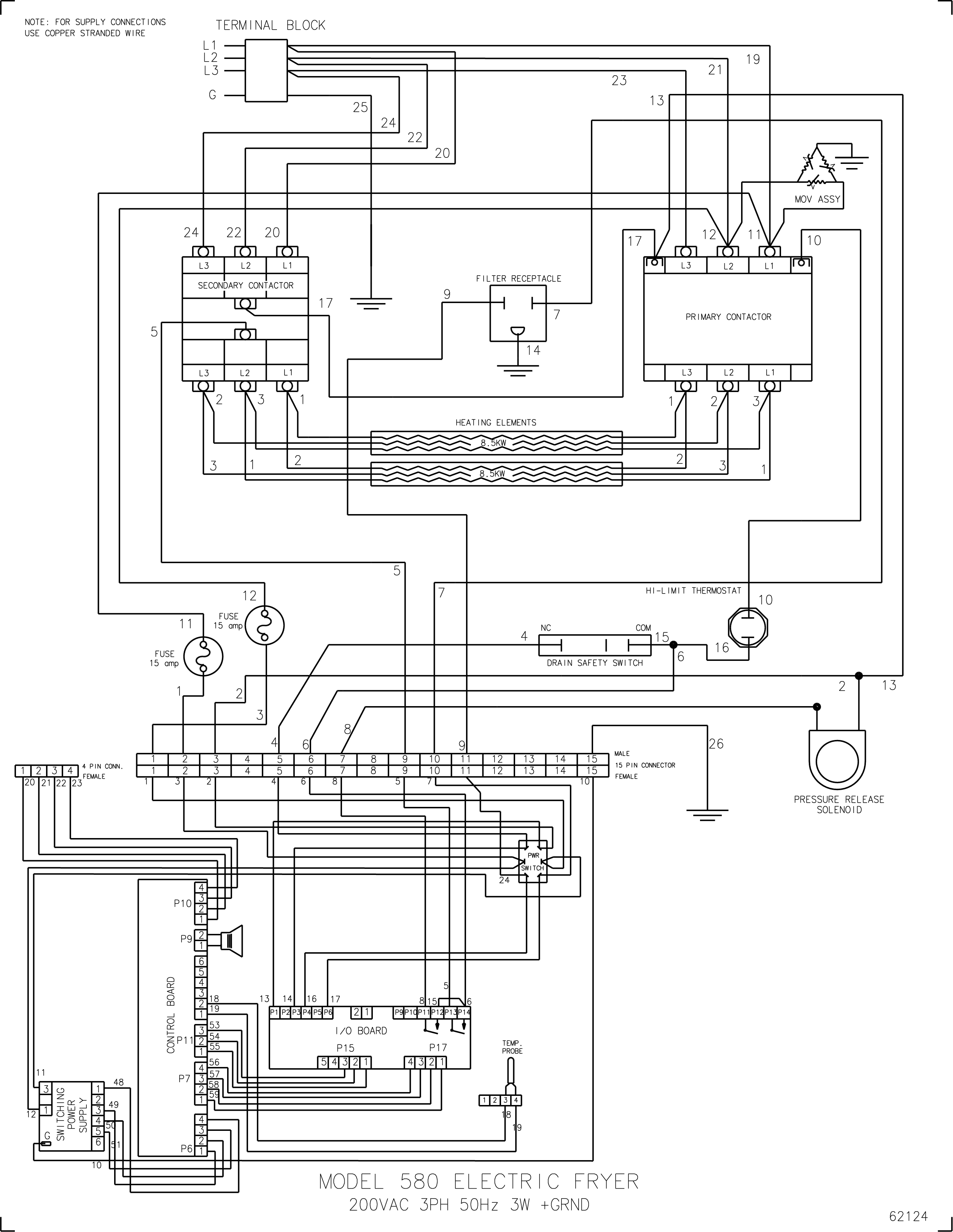
PFE 580 200VAC, 50Hz, 3 phase, 3W+G Wiring Diagram
PFE 580 and 581 208-240VAC, 50-60Hz, 17kW, 3W+G Wiring Diagram
Related Content
Information about the 580 and 582 Fryers
Installing the 580 and 582 Fryers
Operating the 580 and 582 Fryers
Programming the 580 and 582 Fryers
Troubleshooting the 580 and 582 Fryers
Cleaning the Safety Relief Valve
Calibrating and Cleaning the Pressure Gauge
SMS Control Special Programming
Testing and Replacing the Power/Pump Switch
Troubleshooting the PFE 580 or 582 E-41 Control Programming Lost Error Code
Replacing the High Temperature Limit Control
Testing and Replacing the Fuse Holders
Replacing the Heating Elements
Replacing the Temperature Probe
Troubleshooting the PFE 580 or 582 E-5 Oil Overheating Error Code
Troubleshooting the PFE 580 or 582 E-6 Temperature Probe Error Code
Troubleshooting the PFE 580 or 582 No Heat Error Code
Replacing the Drain Microswitch
Replacing the Lid Counterweight Cables
Adjusting the Lid Magnet Plate
Replacing the Nylatron Slides (Cam Slide Filler)
Reference