Troubleshooting the W-7 Low Amps Warning
Overview
The W7 low amps error occurs when an amp draw lower than
W-7 Errors
-
W-7U: Indicates a low amps condition in the upper heater.
-
W-7L: Indicates a low amps condition in the lower heater.
-
W-7M: Indicates a low amps condition in both heaters.
When the W-7 low amps error occurs, the amp draw ratings for the heating element with the issue will be displayed on the screen. The low amp value will be flashing.
For example, " W-7
Call Avoidance
To help the end user resolve the issue without a service call:
-
Check Power Cords: Unplug and reconnect the power cord to ensure there is no low voltage condition.
-
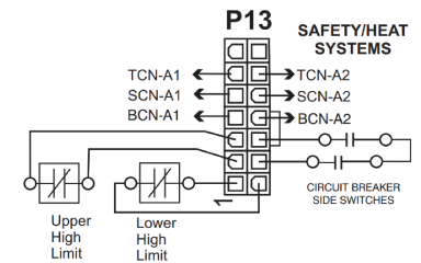
Check Breakers: Verify that the breakers are not tripped. Turn the breaker off and back on to ensure proper contact.
Field Troubleshooting
If call avoidance steps do not resolve the issue, proceed with the following field troubleshooting steps:
Recommended Parts:
CFE 5XX Open Fryer Series
-
Heating elements
-
Contactors
-
Amp sensors
-
Breaker
-
Bus bars
-
Control board
-
Wire
Recommended Tools:
-
Cross tip screwdriver
-
Multimeter
-
Amp clamp
Troubleshooting the Heating Elements and Amp Sensors
-
Check Error Log and Amp Draw:
-
Look for a low amps W-7 error message.
-
-
If one or more of the readings are 0, follow below to check amp sensors first, otherwise continue with Step 2.
-
Disconnect power from the fryer.
-
Lower control panel.
-
Disconnect power to control by removing connector P2.
-
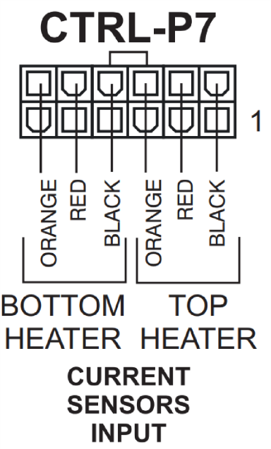
Unplug amp sensors and check resistance of each sensor.
-
Sensors should be 33 Ohms +/- 10% (Cold Check).
-
If any one of the sensors are outside of this range, replace amp sensor.
-
-
-
Check Incoming Voltage:
-
Verify line voltage is present between all three phases at both the incoming side of the primary and secondary contactors for the respective heater
-
-
Check Voltage to Heater(s):
-
With power switch turned on and a demand for heat, check voltage between all three phases for each contactor. If reading is low or 0 for any contactor, proceed to step 4, otherwise check amp draw at each heating element wire from top of contactor. There should be 18.5 amps present on all six wires when there is a demand for heat. If your amp draw is 0 or lower than 10% of this on any wire, check connections, if connections are tight, replace respective heater.
-
-
Check Contactor Coil Voltage:
-
Ensure 24VAC between the blue or yellow wires to the primary contactor coil when the power switch is turned on, if no voltage, ensure control has a demand for heat, check coil wire connections at control and if tight, replace control. Ensure 24VAC between the blue or yellow wires to the secondary contactor coil when there is a demand for heat, if no voltage, ensure control has a demand for heat, check coil wire connections at control and if tight, replace control. If coil voltage is present, contactors pull in, but voltage is low or missing, replace contactor.
-
NOTE: loose connections are sometimes identified by discolored or burnt wire(s). If this situation is found, replace wire and tighten connections (check other connections and tighten to 36 ft-lb. If no fault with voltage, continue to next step.
Other Possibilities
-
AMP Sensor Calibration: Place amp clamp onto amp sensor(s). If your reading is +/- 10% of the reading on the control, perform amp calibration.
Related Content
Troubleshooting the E5 Oil Too Hot Error Code
Troubleshooting the E-6 Main Temperature Probe Failed Error Code
Troubleshooting the E-10 (A-Y) High Limit Tripped Error Code
Troubleshooting the E-19 Protection Probe Failed Warning
Troubleshooting the E-25 Heat Amps Too High Error Code
Troubleshooting the E-26 Heat Amps Locked On Error Code
Troubleshooting the E-30 Circuit Breaker Tripped Error Code
Troubleshooting the E-70B Power Switch or Wiring Failure Error Code
Troubleshooting the E-75 Contactor Near End-of-Life Error Code
Troubleshooting the W-2 Slow Heat Up Warning
Troubleshooting the W-4 Slow Cooking Warning
Troubleshooting the W-6 Slow Cooking Warning
Troubleshooting the W-9 Discard Product Warning
CFE 5XX Replacing the Heating Element
CFE 5XX Replacing High Limit Thermocouple
CFE 5XX Replacing Bottom Probe
CFE-5XX Replacing Temperature/Level/Auxiliary Probe
Reference