The flame sensor should glow a bright red when the pilot is lit and allows the gas valve to open. If it does not sense a flame, it shuts down the gas valve.

|
To avoid electrical shock or property damage, move the power switch to OFF and disconnect power. |
-
Remove the electrical power supplied to the unit.
-
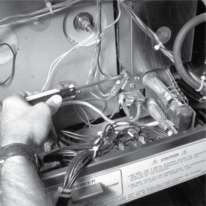
Remove the control panel.

-
Pull the wire off of the terminal of the flame sensor.
-
Using crosshead screwdriver, remove the screw securing the flame sensor assembly, and remove the assembly from the unit.
-
Replace with new assembly in reverse order. Make sure the flame sensor has 1/4” gap between it and the pilot hood.
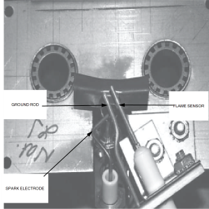
Adjusting the Ignitor and Flame Sensor
For the proper function of the ignitor and flame sensor it is critical that they are at the adjusted properly. The flame rectification, from the flame sensor to the module, should at least be 1.3 microamps.
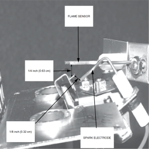
If the burner assembly is removed from the cooker to install and adjust the parts, once the assembly is re-installed, check the spacing of the components again.
Related Content
Replacing the High Temperature Limit Control
Replacing the Temperature Probe
Replacing the Gas Control Valve
Replacing the Ignition Modules
Replacing the Ignitor Assembly
Replacing High Limit Thermocouple
FM07-558 Gas Valve Replacement Kit
Manifold Retrofit Kit Instructions
CE Gas Valve Adjustment Instructions
Air Switch Monitoring Retrofit Kit Instructions
Replacing Gas Valve Assembly With Gas Valve and Solenoid Assembly
Replace Gas Valve Assembly with Gas Valve and Solenoid Assembly
PFG 690 and 691 Temperature Probe CE Instructions
PFG 690/691 Ignition Module Kit
Troubleshooting the PFG 691 E-4 Control Overheating Error Code
Troubleshooting the PFG 691 E-5 Oil Overheating Error Code
Troubleshooting the PFG 691 E-6 Temperature Probe Error Code
Troubleshooting the PFG 691 E-10 High Limit Error Code
Troubleshooting the PFG 691 E-20B No Draft Check Fan Error Code
Troubleshooting the PFG 691 E-20C Ignition Failure Error Code
Troubleshooting the PFG 691 E-20D Ignition Failure Error Code
Reference