Applies to:
![]()
ALL CUSTOMERS
Air Switch Monitoring Retrofit Kit Instructions
Crosstip head screwdriver
Flat-head screwdriver
Electric drill
Wire cutters
Kit number
140149
140248
140249
140245
14418
14749
14750
Estimated Time
1.5 to 2 Hours

|
To avoid electrical shock or property damage, move the power switch to OFF and disconnect power. |
-
Disconnect power from unit.
-
Remove 2 screw securing the control panel.
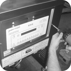
-
Lift panel up and out.
-
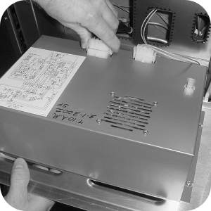
Unplug the connectors going to the control panel.
-
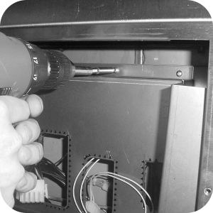
Remove the three screws securing the inner shroud.
-
Pull shroud from the fryer.
-
Locate wirenut with wires no. 82, 70, and 35, and remove wirenut. Wire ties may need to be removed to access wires.
-
Add wire no. 83, from retrofit, to wires 82, 70, and 35, and secure with wirenut.
SN: HH063JJ and below, cut wire 35 and splice in wire no. 83 (from retrofit) onto wire 35.
-
Push other end of wire no. 83 into position 14 on 15-pin connector. (Positions are marked on connector).
-
Locate wire no. 32 from 5-pin connector of transformer and cut wire about 6 inches from connector.
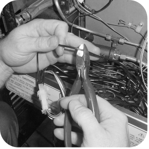
-
Strip back insulation on both cut ends of wire no. 32,
-
and add stripped end of wire no. 84 (from retrofit) to both ends of wire 32, using a wirenut. Wire no. 85 is only found on new production fryers only.

-
Push other end of wire no. 84 into position 13 on 15-pin connector.
-
Replace wire ties as needed.
-
Replace inner shroud and install new control panel.
-
Reconnect to electrical supply and fryer is now ready for use.
Related Content
Replacing the High Temperature Limit Control
Replacing the Temperature Probe
Replacing the Gas Control Valve
Replacing the Flame Sensor Assembly
Replacing the Ignitor Assembly
Replacing the Ignition Modules
Replacing High Limit Thermocouple
PFG-69X & OFG-39X Gas Valve Replacement Kit
Repositioning/Rewiring Air Valves for 220240V Model 690/390 fryers
Repositioning / Rewiring Air Valves for 120V Model 690/390 fryers
FM07-558 Gas Valve Replacement Kit
Manifold Retrofit Kit Instructions
PFG 690/691 Ignition Module Kit
Mounting the OFG 390 and PFG 690 Vacuum Switch
PFG 690 and 691 Temperature Probe CE Instructions
Replace Gas Valve Assembly with Gas Valve and Solenoid Assembly
Replacing Gas Valve Assembly With Gas Valve and Solenoid Assembly
CE Gas Valve Adjustment Instructions
Troubleshooting the PFG 690 and 692 E-4 Control Overheating Error Code
Troubleshooting the PFG 690 and 692 E-5 Oil Overheating Error Code
Troubleshooting the PFG 690 and 692 E-6 Temperature Probe Error Code
Troubleshooting the PFG 690 and 692 E-10 High Limit Error Code
I-Beam Cable Hole Plug Installation
FM08-502 8 Head Replacing KFC Control
FM08-481 8 Head Replacing the Control
Label Application and Location for the 8 Head Fryer
PFG-690/691 & OFG-390/391 Pump Motor Relay Kit
Conversion From C8000 Control to KFC SMS Control
Rear Cover Removal Instructions
Replace Nylatron Slides on PFG 690 and 691
Installing Optional Crumb Basket
PFG 690 and 691 Installing Filter Rinse Hose
PFG 690 Stabilizer Retrofit Instructions
Conversion From Standard 690 Control to S/M Control
PFG 691 C8000 Retrofit Instructions
PFG 690 and 691 Lid Cable Replacement
Operating Instructions for PFG-691/OFG-391 Direct-Connect Oil System
Direct-Connect Retrofit Instructions (For use on fryers after SN: 391-LH016JC & 691-LH029JC)
Replacing the High Temperature Limit Control
Replacing the Temperature Probe
Replacing the Gas Control Valve
Replacing the Flame Sensor Assembly
Replacing the Ignition Modules
Replacing the Ignitor Assembly
Troubleshooting the PFG 691 E-4 Control Overheating Error Code
Troubleshooting the PFG 691 E-5 Oil Overheating Error Code
Troubleshooting the PFG 691 E-6 Temperature Probe Error Code
Troubleshooting the PFG 691 E-10 High Limit Error Code
Troubleshooting the PFG 691 E-20B No Draft Check Fan Error Code
Troubleshooting the PFG 691 E-20C Ignition Failure Error Code
Troubleshooting the PFG 691 E-20D Ignition Failure Error Code
PFG 691 Attaching the Rinse Hose Instructions
Reference
PFG 690 and 692 Inspection and Planned Maintenance
PFG 690 and 692 KFC Annual Inspection Certification