Applies to:
![]()
ALL CUSTOMERS
FM07-558 Gas Valve Replacement Kit
5/8 in. Wrench,
7/8 in. Wrench,
3/8 in. Socket or nut-driver,
1 in. Wrench,
Crosstip head screwdriver,
Wire cutters,
Wire strippers
Kit number
140042
Estimated Time
1 to 1.5 Hours

|
To avoid personal injury or property damage, before starting this procedure, move the main power switch to the off position. Disconnect the main circuit breakers at the circuit breaker box or unplug service cord from wall receptacle. |

|
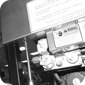
To avoid personal injury or explosion, check piping and fittings for gas leaks. Leaking gas may cause an explosion. |
Check for leaks per Gas Supply. If a leak is detected, shut off gas control valves and repair leak.
-
Remove power from unit.
-
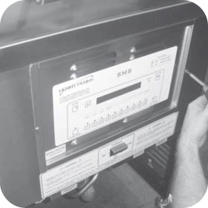
Remove control panel assembly.
-
Remove left side panel.
-
Remove the five screws securing the complete front panel and remove panel from fryer.
-
If present, remove inner heat shield from behind control panel.
-
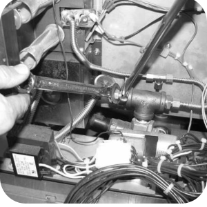
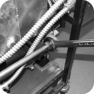
Use a 5/8 in. and 7/8 in. wrench to disconnect burner tube fittings.
-
Use 1 in. wrench to disconnect the main gas line fitting on the left side of the fryer.
-
Remove wire cover from gas valve.
-
Label and remove wires from gas valve. Cut wire ties securing the gas solenoid wires, if unit has solenoid.
-
Use a 3/8 in. socket or nut-driver to remove the nuts securing the high limit bracket and pull high limit assembly from gas valve bracket.
-
Remove screws securing gas valve bracket to frame and remove gas valve assembly from fryer.
-
Locate gas valve assembly from kit and using screws removed in previous step, install new gas valve assembly onto fryer.
-
Locate the three wires in kit. Locate the three labeled gas valve wires on the unit from step 8 and cut and strip ends of the wires. Using the wire nuts, splice the wires from kit onto the gas valve wires, adding 6 inches to all three gas valve wires.
-
Locate the wire cover plate in kit. Align the plate with the bottom of the horizontal frame member and against side of gas valve. Then, using the two self-drilling screws from kit, attach the wire cover plate onto the frame.
-
Locate bushing in kit and snap into place on the wire cover plate.
-
Run gas valve and solenoid wires through bushings.
-
Locate three spade terminals in kit. Crimp the black solenoid wire and wire #9 to a single spade terminal, and crimp the white solenoid wire and wire #39 to a single spade terminal. Crimp the third spade terminal to wire #44.
-
Connect the wires to new gas valve (ALTERNATE GAS VALVE).
-
Locate the wire cover from kit and using the two nuts from kit, attach the wire cover to the fryer.
-
Reattach the high limit and bracket assembly, burner tube fittings and main gas line to new gas valve assembly.
-
Reattach the control heat shield, complete front cover, control panel and left side panel. Installation is now complete.
-
If gas supply is propane, locate the 55282 conversion parts in kit and install on gas valve before installation.
Related Content
Replacing the High Temperature Limit Control
Replacing the Temperature Probe
Replacing the Gas Control Valve
Replacing the Flame Sensor Assembly
Replacing the Ignitor Assembly
Replacing the Ignition Modules
Replacing High Limit Thermocouple
PFG-69X & OFG-39X Gas Valve Replacement Kit
Repositioning/Rewiring Air Valves for 220240V Model 690/390 fryers
Repositioning / Rewiring Air Valves for 120V Model 690/390 fryers
Manifold Retrofit Kit Instructions
PFG 690/691 Ignition Module Kit
Mounting the OFG 390 and PFG 690 Vacuum Switch
PFG 690 and 691 Temperature Probe CE Instructions
Replace Gas Valve Assembly with Gas Valve and Solenoid Assembly
Replacing Gas Valve Assembly With Gas Valve and Solenoid Assembly
Air Switch Monitoring Retrofit Kit Instructions
CE Gas Valve Adjustment Instructions
Troubleshooting the PFG 690 and 692 E-4 Control Overheating Error Code
Troubleshooting the PFG 690 and 692 E-5 Oil Overheating Error Code
Troubleshooting the PFG 690 and 692 E-6 Temperature Probe Error Code
Troubleshooting the PFG 690 and 692 E-10 High Limit Error Code
I-Beam Cable Hole Plug Installation
FM08-502 8 Head Replacing KFC Control
FM08-481 8 Head Replacing the Control
Label Application and Location for the 8 Head Fryer
PFG-690/691 & OFG-390/391 Pump Motor Relay Kit
Conversion From C8000 Control to KFC SMS Control
Rear Cover Removal Instructions
Replace Nylatron Slides on PFG 690 and 691
Installing Optional Crumb Basket
PFG 690 and 691 Installing Filter Rinse Hose
PFG 690 Stabilizer Retrofit Instructions
Conversion From Standard 690 Control to S/M Control
PFG 691 C8000 Retrofit Instructions
PFG 690 and 691 Lid Cable Replacement
Operating Instructions for PFG-691/OFG-391 Direct-Connect Oil System
Direct-Connect Retrofit Instructions (For use on fryers after SN: 391-LH016JC & 691-LH029JC)
Replacing the High Temperature Limit Control
Replacing the Temperature Probe
Replacing the Gas Control Valve
Replacing the Flame Sensor Assembly
Replacing the Ignition Modules
Replacing the Ignitor Assembly
Troubleshooting the PFG 691 E-4 Control Overheating Error Code
Troubleshooting the PFG 691 E-5 Oil Overheating Error Code
Troubleshooting the PFG 691 E-6 Temperature Probe Error Code
Troubleshooting the PFG 691 E-10 High Limit Error Code
Troubleshooting the PFG 691 E-20B No Draft Check Fan Error Code
Troubleshooting the PFG 691 E-20C Ignition Failure Error Code
Troubleshooting the PFG 691 E-20D Ignition Failure Error Code
PFG 691 Attaching the Rinse Hose Instructions
Reference
PFG 690 and 692 Inspection and Planned Maintenance
PFG 690 and 692 KFC Annual Inspection Certification