|
DISPLAY |
CAUSE |
PANEL BOARD CORRECTION |
|---|---|---|
|
“E-4” |
Control board overheating |
Turn switch to OFF position, then turn switch back to ON; if “E-4” continues, the board is getting too hot; check for signs of overheating behind the control panel; once panel cools down the controls should return to normal; if “E-4” persists, have control panel replaced |
|
“E-5” |
Oil overheating |
Turn switch to OFF position, then back to ON; if “E-5” continues, the heating circuits and temperature probe should be checked; once the unit cools down, the controls should return to normal; if “E-5” persists, have control panel replaced |
|
“E-6” |
Temperature probe failure |
Turn switch to OFF position, then back to ON; if the “E-6” continues, the temperature probe should be checked; once the probe is repaired, or replaced, the controls should return to normal; if “E-6” persists, have control panel replaced |
|
“E-41” |
Programming failure |
Turn switch to OFF position, then back to ON; if display shows “E-41”, the control should be re- initialized (See Programming Section) if the error code persists, have control panel replaced |
|
“E-71” |
Pump motor relay failure or wiring problem |
Replace relay if contacts are stuck closed; check wiring on POWER/PUMP switch, or at wall receptacle; L1 and N may be reversed |
| “E-32, FAN FAIL ERROR, CHECK BLOWER, CLEAN DILUTIONBOX, CALL HENNY PENNY SERVICE” | Air pressure switch open; clogged dilution box or faulty blower; open drain switch; open high limit |
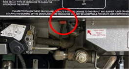
Clean dilution box or replace blower if necessary; have drain switch checked; allow oil to cool and reset high limit or have high limit checked. Resetting High Limit:
|
CE Only - Along with the previous error codes, CE units have the following self-diagnostic error codes:
|
DISPLAY |
CAUSE |
PANEL BOARD CORRECTION |
|---|---|---|
|
“E-10” |
High limit |
Allow oil to cool, and then reset the high limit. If the high limit does not reset, the high limit must be replaced. To reset the high limit:
|
|
“E-15” |
Drain switch |
Close the drain, using the drain valve handle; if display still shows “E-15”, have the drain microswitch checked |
|
“E-20A” |
Air pressure switch failure |
Press the timer button to try the ignition process again, and if “E-20A” persists, call Henny Penny’s Service (stuck closed) Department |
| “E-20B” | Draft fan or air pressure switch failure (stuck open) | Press the timer button to try the ignition process again, and if “E-20B” persists, call Henny Penny’s Service Department |
|
“E-20C” |
Left gas module failure |
Press the timer button to try the ignition process again, and if “E-20C” persists, call Henny Penny’s Service Department |
| “E-20D” | Right module failure | Press the timer button to try the ignition process again, and if “E-20D” persists, call Henny Penny’s Service Department |
|
“E-20E” |
Both modules failure |
Press the timer button to try the ignition process again, and if “E-20E” persists, call Henny Penny’s Service Department |
| “E-20F” | Left module no flame sense | Press the timer button to try the ignition process again, and if “E-20F” persists, call Henny Penny’s Service Department |
|
“E-20G” |
Right module no flame sense |
Press the timer button to try the ignition process again, and if “E-20G” persists, call Henny Penny’s Service Department |
| “E-20H” | Both modules no flame sense | Press the timer button to try the ignition process again, and if “E-20H” persists, call Henny Penny’s Service Department |


E-20 without a Letter
Cause
Are you getting an E-20 error with no letter after the error, a strong pilot, and good flame rectification?
Solution
Check the solenoid valve for a short. A short in the solenoid valve can cause most of the 24 V system to disconnect.
Try disconnecting pressure solenoid valve or turning pressure off in cooking program to see if ignition problem goes away. If it does, the short in the pressure solenoid was the root cause.
Ensure the flame sensor wires are going to the correct ignition module.
Related Content
Information about the 691 Fryers
Troubleshooting the 691 Fryers
Cleaning the Safety Relief Valve
Inspecting the Counterweight Cables
FM08-481 8 Head Replacing the Control
PFG 691 C8000 Retrofit Instructions
Troubleshooting the PFG 691 E-41 Control Programming Lost Error Code
Replacing the High Temperature Limit Control
Replacing the Temperature Probe
Replacing the Gas Control Valve
Replacing the Flame Sensor Assembly
Replacing the Ignition Modules
Replacing the Ignitor Assembly
Replacing High Limit Thermocouple
FM07-558 Gas Valve Replacement Kit
Manifold Retrofit Kit Instructions
CE Gas Valve Adjustment Instructions
Air Switch Monitoring Retrofit Kit Instructions
Replacing Gas Valve Assembly With Gas Valve and Solenoid Assembly
Replace Gas Valve Assembly with Gas Valve and Solenoid Assembly
PFG 690 and 691 Temperature Probe CE Instructions
PFG 690/691 Ignition Module Kit
Troubleshooting the PFG 691 E-4 Control Overheating Error Code
Troubleshooting the PFG 691 E-5 Oil Overheating Error Code
Troubleshooting the PFG 691 E-6 Temperature Probe Error Code
Troubleshooting the PFG 691 E-10 High Limit Error Code
Troubleshooting the PFG 691 E-20B No Draft Check Fan Error Code
Troubleshooting the PFG 691 E-20C Ignition Failure Error Code
Troubleshooting the PFG 691 E-20D Ignition Failure Error Code
Replacing the Drain Microswitch
Replacing the Drain Valve and Extension
Testing and Replacing the Power/Pump Switch
Replacing the Solenoid Below the Counter
Replacing the Solenoid Above the Counter
PFG-690/691 & OFG-390/391 Pump Motor Relay Kit
PFG 690 and 691 Installing Filter Rinse Hose
Direct-Connect Retrofit Instructions (For use on fryers after SN: 391-LH016JC & 691-LH029JC)
Operating Instructions for PFG-691/OFG-391 Direct-Connect Oil System
PFG 691 Attaching the Rinse Hose Instructions
Troubleshooting the PFG 691 Oil Not Pumping
Troubleshooting the PFG 691 E-15 Drain Open Error Code
Replacing the Lid Counterweight Cables
Calibrating and Cleaning the Pressure Gauge
I-Beam Cable Hole Plug Installation
Replace Nylatron Slides on PFG 690 and 691
PFG 690 and 691 Lid Cable Replacement
Label Application and Location for the 8 Head Fryer
Installing Optional Crumb Basket
PFG 690 Stabilizer Retrofit Instructions
Reference