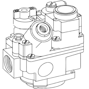
PFG 600 Gas Control Valve
The gas control valve regulates the flow of gas to the pilot and the main burner. The valve consists of: gas regulator, magnetic plug, pilot gas tube, gas valve knob, pilot adjustment cap and screw, gas outlet and inlet ports, thermocouple connector, and electrical connection. The gas control valve also has a dial reference point- OFF / PILOT / ON.

|
To avoid personal injury or property damage, before starting this procedure, move the main power switch to the off position. Disconnect the main circuit breakers at the circuit breaker box or unplug service cord from wall receptacle. |
|
NOTICE - |
If converting from natural gas to propane gas or from propane gas to natural gas, conversion must be done by a qualified service technician. |
Operator Replacement
| Test Volts/Phase | Results |
| Volt - 50/60 Hz | 2350 ohms |
| 240 volt - 50/60 Hz | 880 ohms |
| Volt - 50/60 Hz | 7 ohms |
Regulator Spring Replacement
-
Remove the screw cap to the regulator.
-
Remove the plastic interior screw cap and spring.
-
Use the gas control valve manufacturer's instructions from containing the regulator spring, and follow the directions.
Adjusting Pilot Burner
|
NOTICE - |
The gas supply must be reconnected and turned on. The service cord must be plugged into the receptacle and the circuit breaker on. |
|
NOTICE - |
The flame should be set high enough to surround the top of the thermocouple. |
The pilot burner is a preset at the factory. Unit may require resetting at the time of installation.
-
Remove the pilot adjustment cap.
-
Use a small flat screwdriver and rotate the adjustment screw counterclockwise to increase the size of the flame. Rotate clockwise the adjustment screw to decrease the size of the flame.
Adjusting Regulator
|
NOTICE - |
Gas pressure regulator has been set by manufacturer and should not be adjusted by user. |
The pressure regulator is preset at the factory. Unit may require resetting at the time of installation.
-
Turn gas valve to OFF position.
-
Attach a manometer to the gas control valve at the pressure tap.
-
Turn gas valve knob to PILOT, light and turn to ON.
-
Remove the regulator adjustment screw cap.
-
Rotate the adjustment screw counterclockwise to increase the column indicated on the manometer or rotate clockwise to lower the column indicated.
-
Turn gas valve knob to OFF and remove manometer.
-
Replace the regulator adjustment screw cap.
-
Turn gas valve knob to PILOT and relight. Leak test with soap and water solution.
Related Content
Replacing the High Temperature Limit Control
Checking the Temperature Probe Calibration for Chick-fil-A
Replacing the Temperature Probe
Calibrating The Standard Single Stage Thermostat
Replacing the Gas Burner Assembly
Replacing the Main Power Switch
PFG 600 SSI Fryers Gas Valve Replacement Kit
Direct connect retrofit PFG 600
Direct connect retrofit PFG-600
PFG 600 Ignition Module Retrofit Kit
Temperature Probe Gauge Instructions
Troubleshooting E-1 Frypot Protection System (FPS)
Troubleshooting the PFG 600 E-12 FPS Probe Failure Error Code
Troubleshooting Oil Melting or Heating Slowly
Troubleshooting the PFG 600 E-20C No PV Error Code
Troubleshooting the PFG 600 E-20D Ignition Failure Error Code
Troubleshooting the PFG 600 E-92 24V Fuse Error Code
Reference