Electric Drill with Crosstip Head
Adjustable wrench
Kit number
14219
Estimated Time
30 Minutes to 1 Hour
-
Disconnect Power.
-
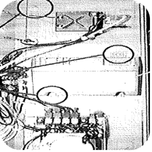
Open control panel to access inside.
-
Use ignition module #21318 as a template. market the locations of the two holes.
-
Drill (2) 7/32 in. holes.
-
Drill (1) 1/2 in. hole.
-
Mount module #21318 using screws and nuts form the kit.
-
Mount reset switch #21317 in 1/2 in hole.
-
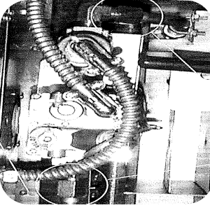
Loosen gas valve assembly at two locations.
-
Remove pilot tube.
-
Replace existing gas valve with gas valve #21316.
-
Remove heat shield.
-
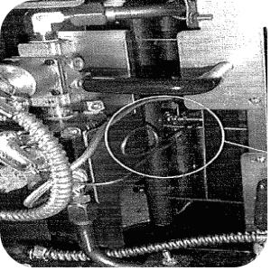
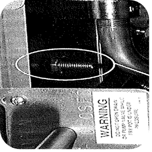
Loosen burner assembly hold-down screw. figure 3.
-
Slide out burner assembly far enough to remove thermocouple and pilot bracket assembly. Figure 4.
-
Replace with new ingitor/bracket assembly.
-
Re-install burner assembly and re-tighten hold-down screw.
-
Wire the unit using diagram #55318.
-
Remove wire 14.
-
Re-install heat shield.
-
Re-install new gas valve assembly.
-
Re-install control panel.
-
Only use the ignition reset switch if the unit is disconnected from the gas supply, or if the unit is shut off for a long period of time (i.e. over a weekend), due to air may be in the gas lines.
Related Content
Replacing the High Temperature Limit Control
Checking the Temperature Probe Calibration for Chick-fil-A
Replacing the Temperature Probe
Calibrating The Standard Single Stage Thermostat
Replacing the Gas Burner Assembly
Replacing the Main Power Switch
PFG 600 SSI Fryers Gas Valve Replacement Kit
Direct connect retrofit PFG 600
Direct connect retrofit PFG-600
PFG 600 Ignition Module Retrofit Kit
Temperature Probe Gauge Instructions
Troubleshooting E-1 Frypot Protection System (FPS)
Troubleshooting the PFG 600 E-12 FPS Probe Failure Error Code
Troubleshooting Oil Melting or Heating Slowly
Troubleshooting the PFG 600 E-20C No PV Error Code
Troubleshooting the PFG 600 E-20D Ignition Failure Error Code
Troubleshooting the PFG 600 E-92 24V Fuse Error Code
Direct connect oil system operating instructions
Electronic C2000 Simple Control Retrofit Kit
Installation of PFG 600 and PFG 600 SSI FM07-366 Electromechanical to C1000 Retrofit
PFG 600 SSI Electronic C1000 to C8000 Retrofit Kit
4 Head PFE 500/ PFG 600 Removing the Lid
RLink programming instructions
Pressure Assist Kit Installation
PFE 500/PFG 600 Wi-Fi Verification and Troubleshooting Instructions
PFE 500/PFG 600 Hybrid Control Installation Instructions
2nd Generation Radio for SMS: Hardware Installation
2nd Generation Radio for SMS: Software Update
FM08-748 2nd Generation Radio for SMS: Troubleshooting
Instructions for Fryer Control Replacement Kits
SMS 20 Auto Polish Programming Instructions
SAE Thread Filter Pump Installation
Pre VA SAE Thread Filter Pump Installation
Hybrid Control and Wi-Fi Installation
Reference