1 in. Wrench
15/16 in. Wrench
3/8 in. Wrench
7/16 in. Wrench
Crosstip head screwdriver
Kit number
140043
Estimated Time
1 Hour

|
To avoid personal injury or property damage, before starting this procedure, move the main power switch to the off position. Disconnect the main circuit breakers at the circuit breaker box or unplug service cord from wall receptacle. |
-
Drain oil from vat.
-
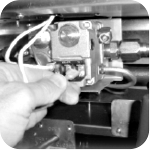
Open door to fryer, label and remove the gas control valve wires.
-
Disconnect gas supply line (28) from the connector (24) at contorl valve.
-
Loosen the two screws(13) on the heat shield deflector (9) on the firebox and flue assembly.
-
Raise the deflector to its highest position.

-
Re-tighten screws (13) to hold the heat shield deflector in the high position.
-
Ensure the fry vat is empty and then turn the filter valve rod to the OPEN position.
-
Remove U-bolt from rinse hose bracket.
-
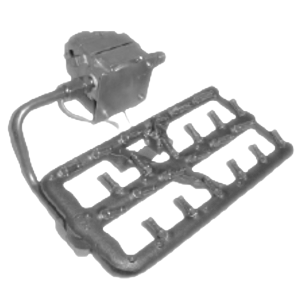
Remove the entire gas burner assembly by lifting and pulling toward front of fryer.
-
Remove gas line, pilot tube and thermocouple from gas valve and remove gas valve and bracket from burner assembly.
-
Remove the gas line from the burner and locate new gas line and elbow in kit.
-
Replace the gas line on the burner.
-
Assemble new heat shield onto new gas valve. Use spacers and screws provided from the kit.
-
Install new gas valve and bracket on burner assembly. If gas supply is propane, use 55282 conversion part and install on gas valve before installation.
-
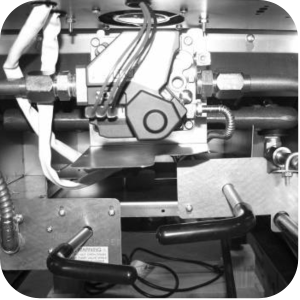
Set burner assembly onto cradle inside of fryer and install U-bolt to rinse hose bracket and gas line.
-
Turn the filter valve handle to the CLOSED postiion.
-
Loosen the two screws (13) which are holding the heat shield deflector (9) in the high position and lower it to the normal operating position.
-
Tighten the two screws (13) on the heat shield).
-
Connect gas supply line (28) to the gas control valve connector (24).
-
Remove control panel and let panel rest of flanges.
-
Replace wires TR-G and PV-MV with the new wires from kit.
-
Install the wires onto gas conrol valve, ensure the wires match the terminals on the new gas valve.
-
Uncap and reconnect the main gas supply line to the fryer. Turn on the main gas supply.
-
Connect the service cord to the wall receptacle or close circuit breakers.
-
Unit is now ready for use.
Related Content
Replacing the High Temperature Limit Control
Checking the Temperature Probe Calibration for Chick-fil-A
Replacing the Temperature Probe
Calibrating The Standard Single Stage Thermostat
Replacing the Gas Burner Assembly
Replacing the Main Power Switch
Direct connect retrofit PFG 600
Direct connect retrofit PFG-600
PFG 600 Ignition Module Retrofit Kit
Temperature Probe Gauge Instructions
Troubleshooting E-1 Frypot Protection System (FPS)
Troubleshooting the PFG 600 E-12 FPS Probe Failure Error Code
Troubleshooting Oil Melting or Heating Slowly
Troubleshooting the PFG 600 E-20C No PV Error Code
Troubleshooting the PFG 600 E-20D Ignition Failure Error Code
Troubleshooting the PFG 600 E-92 24V Fuse Error Code
Direct connect oil system operating instructions
Electronic C2000 Simple Control Retrofit Kit
Installation of PFG 600 and PFG 600 SSI FM07-366 Electromechanical to C1000 Retrofit
PFG 600 SSI Electronic C1000 to C8000 Retrofit Kit
4 Head PFE 500/ PFG 600 Removing the Lid
RLink programming instructions
Pressure Assist Kit Installation
PFE 500/PFG 600 Wi-Fi Verification and Troubleshooting Instructions
PFE 500/PFG 600 Hybrid Control Installation Instructions
2nd Generation Radio for SMS: Hardware Installation
2nd Generation Radio for SMS: Software Update
FM08-748 2nd Generation Radio for SMS: Troubleshooting
Instructions for Fryer Control Replacement Kits
SMS 20 Auto Polish Programming Instructions
SAE Thread Filter Pump Installation
Pre VA SAE Thread Filter Pump Installation
Hybrid Control and Wi-Fi Installation
Reference